
User's Manual
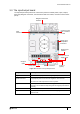
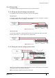
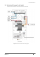
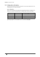
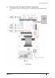
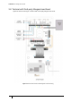
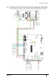
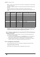
Table Of Contents
- Introduction
- Mounting the Terminal
- Wiring the Terminal
- 3.1 Cabling requirements
- 3.2 The front board
- 3.3 The input/output board
- 3.4 Wiring locks
- 3.5 Terminal with Request to Exit switch
- 3.6 Configuration information
- 3.7 Terminal with third-party OSDPv2 read head
- 3.8 Terminal with third-party Wiegand read head
- 3.9 Terminal with DIU 230 and third-party Wiegand read head
- 3.10 Configuration information
- 3.11 S700e with S700s exit reader
- 3.12 S700 with DIU 210 and S700s exit reader
- 3.13 S700 terminal with DIU 230
- 3.14 Tamper detection on reader inputs
- Reader Network Configuration
- AC2000 Software Configuration
- The System Configuration Menu
- S700 Operational Modes
- Appendix 1 Updating Firmware
- Appendix 2 Broadcast and Timezone Priorities
- Appendix 3 Loading card definitions

S700-IM-0088-1.72
CHAPTER 3 : Wiring the Terminal
36
3.6 Configuration information
Wiring an S700 terminal with a Request to Exit switch is a basic wiring configuration and is not
recommended for use on high security doors.
Input configuration
Table 11: S700 and Request to Exit switch input configuration illustrates the configuration and
operation of the inputs on the terminal when it is configured with a Request to Exit switch.
Note: Wiring diagram is for the installation of the S700 terminal in Door Mode.
Input number Input function Default input trigger state change
0 Door position short => open
1 Lock position short => open
2 Request to exit switch open => momentary short => open
3 Spare/Interlock short => open
Table 11: S700 and Request to Exit switch input configuration