
User's Manual
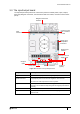
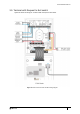
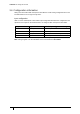
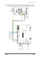
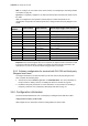
Table Of Contents
- Introduction
- Mounting the Terminal
- Wiring the Terminal
- 3.1 Cabling requirements
- 3.2 The front board
- 3.3 The input/output board
- 3.4 Wiring locks
- 3.5 Terminal with Request to Exit switch
- 3.6 Configuration information
- 3.7 Terminal with third-party OSDPv2 read head
- 3.8 Terminal with third-party Wiegand read head
- 3.9 Terminal with DIU 230 and third-party Wiegand read head
- 3.10 Configuration information
- 3.11 S700e with S700s exit reader
- 3.12 S700 with DIU 210 and S700s exit reader
- 3.13 S700 terminal with DIU 230
- 3.14 Tamper detection on reader inputs
- Reader Network Configuration
- AC2000 Software Configuration
- The System Configuration Menu
- S700 Operational Modes
- Appendix 1 Updating Firmware
- Appendix 2 Broadcast and Timezone Priorities
- Appendix 3 Loading card definitions

S700 Installation Manual
31
3.3 The input/output board
The input/output board provides the connections points for terminal power, inputs, outputs,
third-party Wiegand read heads, communications with exit readers, and Door Interface Units
(DIUs).
Figure 16 Illustration of the Input/Output board
Component Description
Wiegand interface Interface for third-party exit heads using Wiegand protocol
Supply Input and
Speaker Connector
12 Vdc or 24 Vdc power, either from a CEM Door Interface Unit (DIU) or
an appropriate power source must be supplied to this connector
This is also the audio output for the internal speaker.
Output 0 Lock output, either 12 Vdc or 24 Vdc: voltage provided to relay common
connection can be taken internally through the J9 Supply Input terminal or
externally
Ribbon connector Connects the I/O PCB to the front PCB
Output 1 Spare output. This output is also used when configuring the reader in
interlock mode.
Table 10: Description of I/O board components
Input
connector
Wiegand read head
interface
Comms to exit/
DIU or Comms
to Host
Supply Input
and Speaker
Output 0
Ribbon connector
Connector
Safety GND
Output 1
Supply Input
Current
(spare)
(lock)
12 Vdc / 24 Vdc
Supply Input