
User's Manual
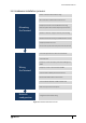

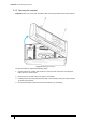
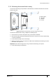
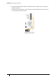
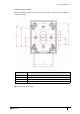

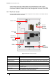
Table Of Contents
- Introduction
- Mounting the Terminal
- Wiring the Terminal
- 3.1 Cabling requirements
- 3.2 The front board
- 3.3 The input/output board
- 3.4 Wiring locks
- 3.5 Terminal with Request to Exit switch
- 3.6 Configuration information
- 3.7 Terminal with third-party OSDPv2 read head
- 3.8 Terminal with third-party Wiegand read head
- 3.9 Terminal with DIU 230 and third-party Wiegand read head
- 3.10 Configuration information
- 3.11 S700e with S700s exit reader
- 3.12 S700 with DIU 210 and S700s exit reader
- 3.13 S700 terminal with DIU 230
- 3.14 Tamper detection on reader inputs
- Reader Network Configuration
- AC2000 Software Configuration
- The System Configuration Menu
- S700 Operational Modes
- Appendix 1 Updating Firmware
- Appendix 2 Broadcast and Timezone Priorities
- Appendix 3 Loading card definitions

S700-IM-0088-1.72
CHAPTER 3 : Wiring the Terminal
30
There must be enough spare cable left within the enclosure/back box to allow a service
engineer to open the terminal case without straining the RJ45 connector. If the cable is subject
to movement or vibration, stranded ethernet cable, and appropriate connectors, must be used.
3.2 The front board
The front PCB contains the main electronic components of the reader; it is also where ethernet
communications must be connected.
Figure 15 Illustration of the front board
Tamper Switch
Antenna
connector
(DO NOT
DISTURB)
Network link
speed LED
Ethernet
activity LED
RJ45
connector
Ribbon
connector to
the I/O board
Operational
LED
Component Description
RJ45 connector Used for Ethernet communications
Ribbon connector Connects the front PCB to the I/O PCB
Antenna Connector This is used for the PROX antenna. If fitted, DO NOT remove or tamper with
the wires from this connector
Operational LED This light flashes if the reader is operational and working correctly
Ethernet activity LED Flashing green indicates Ethernet activity
Network link LED Orange indicates 100Base-T connection speed - unlit indicates 10Base-T
connection speed
Tamper switch Used to trigger an alarm when the case is opened
Table 9: Description of front board components