
User's Manual
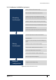

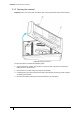
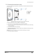

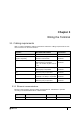
Table Of Contents
- Introduction
- Mounting the Terminal
- Wiring the Terminal
- 3.1 Cabling requirements
- 3.2 The front board
- 3.3 The input/output board
- 3.4 Wiring locks
- 3.5 Terminal with Request to Exit switch
- 3.6 Configuration information
- 3.7 Terminal with third-party OSDPv2 read head
- 3.8 Terminal with third-party Wiegand read head
- 3.9 Terminal with DIU 230 and third-party Wiegand read head
- 3.10 Configuration information
- 3.11 S700e with S700s exit reader
- 3.12 S700 with DIU 210 and S700s exit reader
- 3.13 S700 terminal with DIU 230
- 3.14 Tamper detection on reader inputs
- Reader Network Configuration
- AC2000 Software Configuration
- The System Configuration Menu
- S700 Operational Modes
- Appendix 1 Updating Firmware
- Appendix 2 Broadcast and Timezone Priorities
- Appendix 3 Loading card definitions

29
Chapter 3
Wiring the Terminal
3.1 Cabling requirements
Table 7: Terminal installation cabling requirements outlines the cabling requirements for each
of the connectors on the S700 terminal.
3.1.1 Ethernet communications
Ethernet communications must be cabled and terminated for 10/100Base-T operation
according to IN ANSI/TIA/EIA-568-A / TIA/EIA-568-B.
Purpose Recommended Cable Connector
Ethernet comms CAT 6 RJ45
12 Vdc or 24 Vdc power
supplied separately
Recommend using a CEM Door
Interface Unit 210/230
16 AWG Screw
Terminal
Inputs Belden 95XX (24 AWG shielded
twisted pairs) or equivalent
(XX = the number of pairs from 01
- 50)
16 AWG Screw
Terminal
Outputs Belden 9462 (22 AWG shielding
twisted pair) or equivalent
16 AWG Screw
Terminal
Connection with exit reader or
DIU
Belden 8723 (22 AWG shielded
twisted 2-pair) or equivalent
16 AWG Screw
Terminal
Wiegand Belden 9514 (7 x 22 AWG), Alpha
1229C(9 x 22 AWG) or equivalent
16 AWG Screw
Terminal
Serial Comms Belden 8723 (22 AWG shielded
twisted 2-pair) or equivalent
16 AWG Screw
Terminal
Table 7: Terminal installation cabling requirements
Type Cable Connector Location
Host CAT6 RJ45 Socket Terminal board
Table 8: Ethernet host