
User's Manual
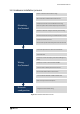
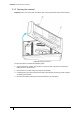
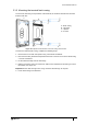
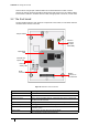
Table Of Contents
- Introduction
- Mounting the Terminal
- Wiring the Terminal
- 3.1 Cabling requirements
- 3.2 The front board
- 3.3 The input/output board
- 3.4 Wiring locks
- 3.5 Terminal with Request to Exit switch
- 3.6 Configuration information
- 3.7 Terminal with third-party OSDPv2 read head
- 3.8 Terminal with third-party Wiegand read head
- 3.9 Terminal with DIU 230 and third-party Wiegand read head
- 3.10 Configuration information
- 3.11 S700e with S700s exit reader
- 3.12 S700 with DIU 210 and S700s exit reader
- 3.13 S700 terminal with DIU 230
- 3.14 Tamper detection on reader inputs
- Reader Network Configuration
- AC2000 Software Configuration
- The System Configuration Menu
- S700 Operational Modes
- Appendix 1 Updating Firmware
- Appendix 2 Broadcast and Timezone Priorities
- Appendix 3 Loading card definitions

S700-IM-0088-1.72
CHAPTER 2 : Mounting the Terminal
26
6. Re-attach the input/output Printed Circuit Board (PCB) to the back casing, ensuring you
replace the spacers.
7. Connect the internal speaker to the I/O board. The yellow speaker wires can be wired to
the J6 speaker terminal in any order.
Figure 13 Speaker wiring