
User's Manual
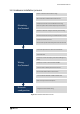
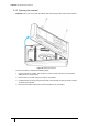
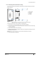
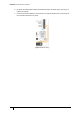
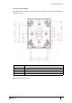
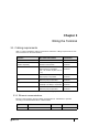
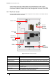
Table Of Contents
- Introduction
- Mounting the Terminal
- Wiring the Terminal
- 3.1 Cabling requirements
- 3.2 The front board
- 3.3 The input/output board
- 3.4 Wiring locks
- 3.5 Terminal with Request to Exit switch
- 3.6 Configuration information
- 3.7 Terminal with third-party OSDPv2 read head
- 3.8 Terminal with third-party Wiegand read head
- 3.9 Terminal with DIU 230 and third-party Wiegand read head
- 3.10 Configuration information
- 3.11 S700e with S700s exit reader
- 3.12 S700 with DIU 210 and S700s exit reader
- 3.13 S700 terminal with DIU 230
- 3.14 Tamper detection on reader inputs
- Reader Network Configuration
- AC2000 Software Configuration
- The System Configuration Menu
- S700 Operational Modes
- Appendix 1 Updating Firmware
- Appendix 2 Broadcast and Timezone Priorities
- Appendix 3 Loading card definitions

S700 Installation Manual
21
1.8 Hardware installation process
Mounting
the Terminal
Wiring
the Terminal
Network
conguration
Remove screws from the S700 front casing
Disconnect ribbon cable from the back I/O board
If required, remove the I/O board from the back casing
Note: The speaker wires must be temporarily disconnected
Drill holes in the back casing for cable entry and mounting
Mount the terminal back casing to the tted back box or wall
If required, re-t the I/O board
Reconnect the speaker wires if they have been disconnected
Connect the input devices to the I/O board terminals
Connect the lock
If required, connect a third-party exit read head: Wiegand or
OSDP
If required, connect an S700 exit reader and DIU
Connect 12 Vdc or 24 Vdc power to the I/O board
Reconnect the ribbon cable to the I/O board
Connect either the Ethernet or RS485 network cable
Fit the security screws and side panels
Congure terminal network setting
Figure 10 Hardware installation flow chart