
User's Manual
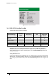
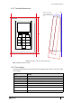
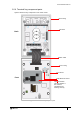
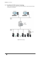
Table Of Contents
- Introduction
- Mounting the Terminal
- Wiring the Terminal
- 3.1 Cabling requirements
- 3.2 The front board
- 3.3 The input/output board
- 3.4 Wiring locks
- 3.5 Terminal with Request to Exit switch
- 3.6 Configuration information
- 3.7 Terminal with third-party OSDPv2 read head
- 3.8 Terminal with third-party Wiegand read head
- 3.9 Terminal with DIU 230 and third-party Wiegand read head
- 3.10 Configuration information
- 3.11 S700e with S700s exit reader
- 3.12 S700 with DIU 210 and S700s exit reader
- 3.13 S700 terminal with DIU 230
- 3.14 Tamper detection on reader inputs
- Reader Network Configuration
- AC2000 Software Configuration
- The System Configuration Menu
- S700 Operational Modes
- Appendix 1 Updating Firmware
- Appendix 2 Broadcast and Timezone Priorities
- Appendix 3 Loading card definitions

S700 Installation Manual
17
1.6.1 Terminal dimensions
100
142
Wall
8.0
o
15
30
48
Note the angle of the
reader to the wall, which
is represented by the blue
line
Figure 7 Illustration of S700, including dimensions
Note: All dimensions are in mm.
1.6.2 Part ratings
The S700 has been tested and operates within the following ranges, which are shown in Table
4: Part ratings.
Part Rating
Supply Voltage (Vdc) 9 to 28
Power (W) Typical: 2.4 / Peak: 4.8
Inputs Four analogue inputs - voltage supplied
Comms to exit reader RS485 serial comms / Wiegand protocol
Comms to system host 10/100 Base-T TCP/IP CAT6 / RS485 serial comms
Dry contacts output 24 Vdc @ 2 A
Operating temperature
(°C)
-20 to +70 (-4 °F to +158 °F)
IP rating IP65
Table 4: Part ratings