
Quick Start Guide
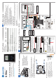

Wiring Configuration: S700e + DIU200 + S700s
3b
GND
0V
SUPPLY
INPUT
NO
RELAY 1
C
NC
NO
RELAY 2
C
NC
0V
0V
0V
SPEAKER
SPEAKER
SUPPLY INPUT
RS232 TX
RS232 RX
RLY 2
RLY 1
LABEL
0V
0V
(0) DOOR POS
(1) LOCK POS
0V
(3)INTERLOCK
0V
(2)REX
DC OUTPUT
0V
SOUNDER
D1
D0
LED RED
LED GREEN
LED AMBER
(1) LOCK POS
J3
J7
J6
J9
J10
RELAY
24V DC MAX.
@2A MAX.
SUPPLY INPUT
12V-24V DC NOM.
@2.5A MAX.
DC OUTPUT
12V @ 1A MAX.
INPUTS
WIEGAND
EXIT/DIU HOST
S700s Reader
SUPPLY INPUT
0V
0V
RS485 2A
DC OUTPUT
RS485 2B
1B
1A
J2
RS485
GND
0V
SUPPLY
INPUT
NO
RELAY 1
C NC NO
RELAY 2
C
NC
0V
0V
0V
SPEAKER
SPEAKER
SUPPLY INPUT
RS232 TX
RS232 RX
0V
0V
(0) DOOR POS
(1) LOCK POS
0V
SUPPLY INPUT
0V
(3)INTERLOCK
0V
(2)REX
DC OUTPUT
0V
SOUNDER
D1
D0
LED RED
LED GREEN
LED AMBER
0V
RS485 2A
DC OUTPUT
RS485 2B
1B
RS485
INPUT WIEGAND EXIT/DIU HOST
1A
RLY 2RLY 1
LABEL
J3 J7
J2
J6
J9
J10
RELAY
24V DC MAX.
@2A MAX.
SUPPLY INPUT
12V-24V DC NOM.
@2.5A MAX.
DC OUTPUT
12V @ 1A MAX.
D17
SW1
ANT 1
D16
J4
J7
LNK 2
LNK 3
LNK 4
LNK 5
1
2
4
8
J1
J5
GPO
COM
REX
DOOR
COM
LOCK
J9
J8
BGU
COM
FIRE
TAMPER
BUZZ –
BUZZ +
COM
485A
485B
RDR +12
J2
LOCK –
COM
MAINS FAIL
LOCKIN 12V/24V
SUPPLY 12V
LOCK +
J4
J3
DIU200
DOOR
POSITION
LOCK
SENSE
REQUEST
TO EXIT
NOTE:
On the DIU, if BGU, FIRE or TAMPER are not used the
connections on J9 must be linked out.
BGU
COM
FIRE
TAMPER
BUZZ –
BUZZ +
BGU
COM
FIRE
TAMPER
BUZZ –
BUZZ +
BGU
COM
FIRE
TAMPER
BUZZ –
BUZZ +
FIRE
BGU
TAMPER
MAGNETIC
LOCK
-
+
PSU 12V
2A min
-
+
Technical Support
Tel: +44 (0)28 90 456656
Sales
cem.sales@tycoint.com
1. On the terminal keypad, quickly tap the right function key at least three times.
Setting the terminal IP address, Subnet mask and Gateway
Checking network status
The network status is continuously displayed on the home screen of the reader.
Terminal has received the onboard database
Terminal has received
configuration settings
from the CDC
Terminal is connected to network using ethernet
Terminal is connected
to the RTC
Configuring the Network
5
The terminal is now connected to the AC2000 system and ready to use.
5. Select Change to edit the selected field.
6. Enter the IP Address, Subnet and Gateway settings using the keypad. Press the left
function key for a '.'
7. To exit settings, press key 0 and select Save to save the new settings, or Quit to
discard changes.
!
!
WARNING - For FCC labelled S700 Terminals
This device complies with Part 15 of the FCC rules. Operation is subject to the following two conditions:
(1) This device may not cause harmful interference, and
(2) This device must accept an interference received, including interference that may cause undesired operation.
This equipment complies with FCC radiation exposure limits set forth for an uncontrolled environment. End
users must follow the specific operating instructions for satisfying RF exposure compliance. This transmitter
must not be collocated or operating in conjunction with any other antenna or transmitter.
Changes or modifications not expressly approved by the party responsible for compliance could void the user's
authority to operate the equipment.
Installation of this device shall be performed by a qualified person in accordance to all local regulations.
This system must be installed within the protected premsie in accordance with the National Electrical Code
(NFPA70), and the local authorities having jurisdiction.
Equipment changes or modifications without the approval of the party responsible for compliance could void the
user's authority to operate the equipment and could create a hazardous condition.
2. Enter the pass code 67670000 to access the Config Menu. After the AC2000 system
setup is complete, the pass code is 6767XXXX, where XXXX is the code set by the system
administrator in Device Configuration.
3. To access the Network Settings menu, press key 5.
4. Select Next to highlight the relevant field.
For more information on the S700, consult the following resources.
Datasheets
http:www.cemsys.com/S700
Installation Manual
http:www.cemsys.com/support
User Guide
http:www.cemsys.com/support
Safety and Regulatory Information
Support
Copyright © 2016 Controlled Electronic Management Systems Limited. All rights reserved.
No part of this publication may be produced without the written permission of CEM Systems Limited.
4
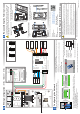
Re-assembling the Terminal
Care should be taken when re-assembling the terminal. The front case
should not be left hanging from the ribbon cable while attached to the
back case. Ensure there is adequate network cable length to reach
the connectors.
Note: Power is supplied by the DIU
2. Ensure the large case o ring and the 4
small o rings are in place. Attach the
front case to back case.
3. Screw the front casing to the back
casing using the four security hex
screws.
4. Clip the side panels onto each side of
the terminal covering each of the
mounting screws.
1. Connect the ribbon cable to the
I/O board.
Cancel Delete
Enter Setup PIN
Next Change
S700: Network settings
IP address
Subnet mask
Gateway
172.16.42.6
255.255.255.0
0.0.0.0
8
5
3
CEM SYSTEMS
1 2 3
4 5 6
7 8
0
9
S700-IG-0087-1.72
Present Card