
User's Manual
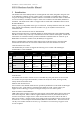

Table Of Contents
- 1 Introduction
- 2 Quick Guide to setting up S610S
- 3 Connecting an S610S Master Reader
- 3.1 Open the S610 reader case
- 3.2 S610S Master Reader 12V Power and Data connections
- 3.3 Extra settings required, made on the reader
- 3.4 Addressing an S610S master reader
- 3.5 S610S Connecting Master Reader Inputs
- 3.6 Monitoring Inputs for Cable Tampers
- 3.7 Using an external read head
- 3.8 S610S Lock and spare output relay connections
- 4 Connecting an S610S to an Exit Reader
- 5 Connecting an S610S to a DIU
- 6 AC2000 Devices Application tasks
- 7 Door Modes
- 8 Interlock
- 9 Other AC2000 software configurations
- 10 S610S onboard diagnostic mode
- 11 Appendix
S610S Manual - Hardware Installer Manual - Version 1.8
4
I
I
l
l
l
l
u
u
s
s
t
t
r
r
a
a
t
t
i
i
o
o
n
n
s
s
S610S readers can be used on an RS485 serial chain as Master and Exit readers. 8
Shows S610S, RS485 data and power connections. 11
Example of used Reader addresses. 12
A screen shot of an S9064 controller Hyper Term session. 13
S610S inputs, (when no DIU present). 13
Sensor fitted with resistors, monitoring Open Closed and tamper conditions. 14
Relay Connector J12 showing typical Maglock configuration. 15
Connecting a Sounder. 16
Shows S610S, RS485data, power and Exit Reader connections. 17
Shows the AC2000 Devices application, Device Type, being updated. 18
Power & RS485 serial connections to a Master Reader 19
Lock and a choice of 12V or 24V lock power 20
AC2000 Door Mode door cycle time sequence of events. 24
During 9-5 MON-FRI only the global PIN is required to gain access. 26
Example of Timezone (TZ) options, AC2000 workstation Time Zone application 27
Reader Time Zones. 27
Shows Device Configuration – Door Time Zone. 28
S610S Time Zone Active options group. 28
AC2000 Passenger Mode card transaction time sequence 32
PIR mode input assembly, normal Request to Exit (REX) behaviour is disabled. 32
Typical wiring for two turnstiles 36
Sample wiring for a uni-directional turnstile barrier with external PSU. 36
Shows an S610E or S610S Master reader connected to a sample bi-directional turnstile. 36
Shows an S610E or S610S Master and Exit reader connected to a sample bi-directional turnstile. 36
Pulse Turnstile, one second or more pulse output 38
Timed Output sequence of S610S reader in Equipment Mode 40
An example of S610S PCB connections used for Equipment Mode. 41
An example of S610S PCB connections used for Equipment Mode. 41
The relays on the S610S change state when powered up. 44
Select an Output, and then enable it. 46
Mapping an input signal to a relay switch. Ensure Local output disabled is unchecked. 47
Sounder connected to a spare relay 47
S610S Menu tree. 49
The address of the reader in the example above is B 50
Connector J5 on S610S is connected to J16 on the S400 exit reader. 55