
User's Manual

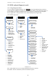
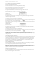
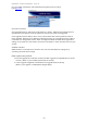

Table Of Contents
- 1 Introduction
- 2 Quick Guide to setting up S610S
- 3 Connecting an S610S Master Reader
- 3.1 Open the S610 reader case
- 3.2 S610S Master Reader 12V Power and Data connections
- 3.3 Extra settings required, made on the reader
- 3.4 Addressing an S610S master reader
- 3.5 S610S Connecting Master Reader Inputs
- 3.6 Monitoring Inputs for Cable Tampers
- 3.7 Using an external read head
- 3.8 S610S Lock and spare output relay connections
- 4 Connecting an S610S to an Exit Reader
- 5 Connecting an S610S to a DIU
- 6 AC2000 Devices Application tasks
- 7 Door Modes
- 8 Interlock
- 9 Other AC2000 software configurations
- 10 S610S onboard diagnostic mode
- 11 Appendix

S610S Manual - Hardware Installer Manual - Version 1.8
52
10.5 Configure Menu
Reader Address - an installer must apply an address to the reader using the keypad configure menu.
Only then can a configuration and offline data base be downloaded to the reader by the controller.
Aux Device(s) - Enable or Disable a DIU, Exit Reader or Exit Keypad. If a card holder is requested
to enter a pin number
Diagnostic Code - used to change the diagnostic PIN used to access the reader diagnostic mode.
Special Option - Manufacturers use only
Door Mode - scroll through the options to select the S610S door mode. This must be done a the
reader as the node can not be down loaded from the system.
Keypad - select No Keypad if PIN numbers are not required.
Force Coldstart - force coldstart refreshes the Off Line database from the controllers.
If problems persist, make sure the controller has a fresh copy of the database before coldstarting the
reader.
Relay State - reverses the state of the relay output0 on the master reader
2
nd
Relay Action - reverses the state of the relay output1 on the master reader
Sounder Action - enable or disable the readers onboard sounder.
A S600s with DIU and slave will use the local sounder for door forced, held, etc only when the
sounder action configuration is enabled locally in the reader configuration menu.
Diagnostic Card - enable or disable the used of a diagnostic card, used to access diagnostic mode
instead of a PIN.
Read Heads - scroll through options. If the reader is failing to read cards, ensure the correct Card
Format is set, only enable a SmartHead, if one present. If a smarthead is connected to the reader it
must be enabled using this menu. See paragraph
10.6 below.
Tamper Values - Adjust optical tamper sensitivity. See paragraph 10.7 below.
LCD Contrast - use to adjust the LCD contrast if required.
10.6 Setting the correct readhead technology
If a reader has stopped reading cards correctly or a new reader will not read cards check the read
head configuration.
If the reader is failing to read cards, ensure the correct Card Format is set, only enable a SmartHead,
if a smarthead is present.
Prox:
Prox head ON or OFF. This is for an antenna connected internally.
H0 and H1 readhead connections are unaffected by this setting.
Card Definition (or Card format)
CEM 26, CEM37, Simplex36, Vancouver34, Watermark (also used for Diester), CEM26,
Wiegand26, Sensormatic37, HID1000, Wiegand34, Wiegand32, Kantech, Sensormatic32.
The correct definition MUST be selected for the card definition being used at the reader.
Smarthead
No Smart head - default, unless you are using a Mirefare reader model.
IEP 14443A - For EXTERNAL (to the reader) Mifare read head
CLRC632 - This is the setting for reading Mifare cards using INTERNAL read head
PICOREAD - If a PICO smarthead is connected to the reader it must be enabled using this menu.