
User's Manual

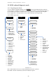
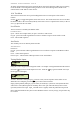
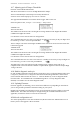
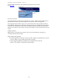

Table Of Contents
- 1 Introduction
- 2 Quick Guide to setting up S610S
- 3 Connecting an S610S Master Reader
- 3.1 Open the S610 reader case
- 3.2 S610S Master Reader 12V Power and Data connections
- 3.3 Extra settings required, made on the reader
- 3.4 Addressing an S610S master reader
- 3.5 S610S Connecting Master Reader Inputs
- 3.6 Monitoring Inputs for Cable Tampers
- 3.7 Using an external read head
- 3.8 S610S Lock and spare output relay connections
- 4 Connecting an S610S to an Exit Reader
- 5 Connecting an S610S to a DIU
- 6 AC2000 Devices Application tasks
- 7 Door Modes
- 8 Interlock
- 9 Other AC2000 software configurations
- 10 S610S onboard diagnostic mode
- 11 Appendix

S610S Manual - Hardware Installer Manual - Version 1.8
51
All other configurations listed can be checked, this is most useful when the reader may be working
in off-line mode. The configuration being used for access control during off-line mode can be
checked at the reader while it is still off-line.
10.4 Test Menu
The Test menu allows the user to perform diagnostic tests on certain aspects of the reader’s
features.
Use the key to toggle through the various test screens. The routine allows the user to test either
the master reader or the exit reader (if fitted). Select the
local device option for the master, or the aux
device (s)
option for the exit reader.
Local Device
The Local Device is normally the Master reader
Local device Test –
Inputs - shows current inputs states, O open C closed or c short circuit.
Keypad - press each reader keypad button in turn to confirm a response on the reader’s LCD.
LEDs - Check LED responses
Aux Device
The Auxiliary Device is normally the Exit reader
Aux devices test –
Read Head –
Keypad - press each Exit reader keypad button in turn to confirm a response on the Master reader’s
LCD.
LEDs - Check LED responses
Remote inputs - DIU and Exit reader Input states can be checked here
Testing Reader Inputs
Using the reader’s keypad; enter Diagnostic mode. See chapter on Diagnostic Mode in this manual.
Select the key to move to the Inputs test screen. Press the key again to hold the screen (an
H will appear on the right)
Activate / deactivate each input open or closed to test, note the response on the reader’s LCD.
When the test is complete, press the key to return to the test menus.
Input_0 (door position) and input_1 (lock status) are normally C (Sensor is closed) when the door
and lock are closed; these inputs will normally show O for open when the door (sensor is in the
open state) and lock are open. Input_2 should not be O (Open) unless the push button is pressed.
Note: Some door hardware may have sensors fitted that work in reverse (rarely), so input states may
be reversed.