
User's Manual
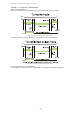
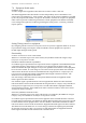
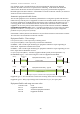
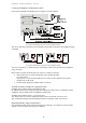
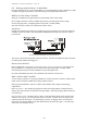
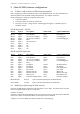
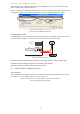
Table Of Contents
- 1 Introduction
- 2 Quick Guide to setting up S610S
- 3 Connecting an S610S Master Reader
- 3.1 Open the S610 reader case
- 3.2 S610S Master Reader 12V Power and Data connections
- 3.3 Extra settings required, made on the reader
- 3.4 Addressing an S610S master reader
- 3.5 S610S Connecting Master Reader Inputs
- 3.6 Monitoring Inputs for Cable Tampers
- 3.7 Using an external read head
- 3.8 S610S Lock and spare output relay connections
- 4 Connecting an S610S to an Exit Reader
- 5 Connecting an S610S to a DIU
- 6 AC2000 Devices Application tasks
- 7 Door Modes
- 8 Interlock
- 9 Other AC2000 software configurations
- 10 S610S onboard diagnostic mode
- 11 Appendix

S610S Manual - Hardware Installer Manual - Version 1.8
46
9.3 Input/output Mapping
Input mapping enables a local input to activate a local output. This option is typically used when a
local sounder or flashing light is needed for an alarm condition.
Mapping an input to an output
Open the AC2000 Devices application and expand the Overview table. Locate the Reader from the
table and expand its options. Select
Configuration.
Use the
Device Configuration, Inputs tab and select the input to be mapped to an output.
After selecting the input, click
Edit, then select from the dropdown dialog the output needed.
Remember to clear the
Local output disabled box. For other options, see below.
Select an Output, and then enable it.
INPUT – OUTPUT MAP
The Input-Output Map option box offers possible output options. If you select an Input the settings
can be viewed or edited. This dialog is most often used to enable Normal input, to trigger a relay or
to map an input to trigger a sounder attached to the DIU. Output options are listed in the dropdown
list (see fig: 8.1c below).
Pulse output – causes the output signal to pulse at 1Hz, e.g. If output is LED it will flash on/off when
triggered.
Remote output disabled – If this option is checked alarms will not be passed to the RTC, and
consequently not recorded by the Access Control system
4 State – Used to enable input monitoring: Open, Closed, Tamper Short and tamper Cut. If this
option is selected, cable tampering of ‘short’ and ‘cut’ will also be detected. Different types of
tamper are not distinguished, but simply reported as tamper. This option is only valid if resistors
have been added to the input cable. See Appendix 16.4 of this manual for information on
resistor/cable configuration.
Invert output – Inverts the out put state. E.g. if your LED is normally OFF going ON, then the LED
will be ON going OFF when the output is triggered.
Normal input – If checked the Normal input is available as a normal or general purpose input.
If this input setting is unchecked then the input is reserved by the AC2000 system.
Local output disabled – Disables the output selected in the drop down box. Clear this option if
mapping to a local output.
No Debounce – For example, if a door slams the door may bounce open again before finally closing
firmly. The first time the door closes will be reported by the system as door closed, if
No Debounce
is checked the second time or bounce will set off a door forced alarm. Leaving No Debounce clear
allows the default debounce time configuration to function.
For more information on configuring Devices on an AC2000 system please see the AC2000
Devices online help or manual.
9.4 Configuring a spare Output Relay
Note: AC2000 software writers refer to relays 0 and 1, but CEM hardware designers often label
relays1 and 2, as on the S610EP PCB. If a DIU is present the Lock Relay on the DIU backplane