
User's Manual
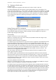
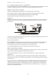
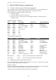
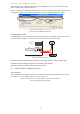
Table Of Contents
- 1 Introduction
- 2 Quick Guide to setting up S610S
- 3 Connecting an S610S Master Reader
- 3.1 Open the S610 reader case
- 3.2 S610S Master Reader 12V Power and Data connections
- 3.3 Extra settings required, made on the reader
- 3.4 Addressing an S610S master reader
- 3.5 S610S Connecting Master Reader Inputs
- 3.6 Monitoring Inputs for Cable Tampers
- 3.7 Using an external read head
- 3.8 S610S Lock and spare output relay connections
- 4 Connecting an S610S to an Exit Reader
- 5 Connecting an S610S to a DIU
- 6 AC2000 Devices Application tasks
- 7 Door Modes
- 8 Interlock
- 9 Other AC2000 software configurations
- 10 S610S onboard diagnostic mode
- 11 Appendix

S610S Manual - Hardware Installer Manual - Version 1.8
45
9
9
O
O
t
t
h
h
e
e
r
r
A
A
C
C
2
2
0
0
0
0
0
0
s
s
o
o
f
f
t
t
w
w
a
a
r
r
e
e
c
c
o
o
n
n
f
f
i
i
g
g
u
u
r
r
a
a
t
t
i
i
o
o
n
n
s
s
9.1 To Edit or Add an input for AED alarm management
Fully configuring an AED is outside the scope of this S610EP manual. For more information on
AED setup Refer to the AC2000 Getting Started manual. See chapter on Devices.
Before attempting to configure an input you must know:-
• The device address
• The input number the sensor is connected to
• The relay or sensor “change of state” which triggers the signal, i.e. Normally Open or
Normally Closed.
S610E input table – No DIU
Device Input # Description Sensor State Typical AED Alarm
Master Input 0 Door Position Closed Door Closed
Master Input 0 Door Position Open Door Forced
Master Input 1 GP or Lock Condition Closed Lock Engaged
Master Input 1 GP or Lock Condition Open Lock Not Engaged
Master Input 2 REX
Master Input 3 GP or Interlock
Slave Input 4 GP
Slave Input 5 GP
Slave Input 6 GP
Slave Input 7 GP
S610E with DIU Input table
Device Input # Description Sensor State Typical AED Alarm
DIU Input 0 Door Position Closed Door Closed
DIU Input 0 Door Position Open Door Forced
DIU Input 1 GP or Lock Condition Closed Lock Engaged
DIU Input 1 GP or Lock Condition Open Lock Not Engaged
DIU Input 2 REX
DIU Input 3 Breakglass Closed Breakglass Reset
DIU Input 3 Breakglass Open Breakglass
DIU Input 4 Fire Alarm Closed Fire Alarm Reset
DIU Input 4 Fire Alarm Open Fire Alarm
DIU Input 5 Mains Power fail Closed Mains OK
DIU Input 5 Mains Power fail Closed Mains Power Fail
DIU Input 6 Battery Low Open DIU Battery Low
DIU Input 7 Enclosure tamper Switch Open Enclosure Tamper
Master Reader 8,9,A,B Spare General Purpose Inputs on Master Reader
Slave Reader C,D,E,F, Spare General Purpose Inputs on Exit Reader
9.2 Disabling an Input using AC2000 software
Open the AC2000 Devices application and expand the Overview table. Locate the device from the
table and expand its options. Select
Configuration.
DISABLE AN INPUT
From the Configuration table highlight an Element, then select Edit you will then be presented with
Edit Element Options, uncheck the Enabled box if the Input is to be disabled.
Typically, if not used, a REX input may be disabled to avoid tampering.