
User's Manual
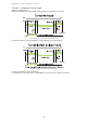
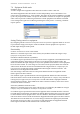
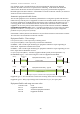
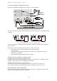
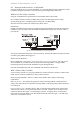
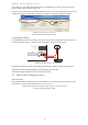
Table Of Contents
- 1 Introduction
- 2 Quick Guide to setting up S610S
- 3 Connecting an S610S Master Reader
- 3.1 Open the S610 reader case
- 3.2 S610S Master Reader 12V Power and Data connections
- 3.3 Extra settings required, made on the reader
- 3.4 Addressing an S610S master reader
- 3.5 S610S Connecting Master Reader Inputs
- 3.6 Monitoring Inputs for Cable Tampers
- 3.7 Using an external read head
- 3.8 S610S Lock and spare output relay connections
- 4 Connecting an S610S to an Exit Reader
- 5 Connecting an S610S to a DIU
- 6 AC2000 Devices Application tasks
- 7 Door Modes
- 8 Interlock
- 9 Other AC2000 software configurations
- 10 S610S onboard diagnostic mode
- 11 Appendix
S610S Manual - Hardware Installer Manual - Version 1.8
43
8
8
I
I
n
n
t
t
e
e
r
r
l
l
o
o
c
c
k
k
8.1 Interlock in Door Mode
Interlock in door mode enables the second output Relay (Relay1) on the reader to be usefully
activated; the output is used to notify another reader, logic control device or interlock controller the
door is active. Options like, Special Cards, REX and Oneshot can apply. This mode can not be
selected from the Door Mode option table. The following settings need to be made. This mode is
supported on Firmware version B1.00.042 or later. For Passenger Mode interlocking, consult the
paragraphs on Passenger Mode interlocking in this manual.
TO APPLY INTERLOCK IN DOOR MODE
Use the workstation Devices application to configure the reader settings. When two readers are
joined to create a “mantrap” or “airlock” both readers must be configured.
Configure the reader’s interlock input
Select the reader from the Devices > Configuration > Inputs
1. Edit Input 3 (or IPB if DIU present) and ensure
Normal setting is clear.
When input 3 (or IPB) is in the open condition the reader will be interlocked and all card
transactions will be denied. Oneshot and REX commands will be allowed.
Configure the reader’s interlock output
2. Edit Configuration > Other > Second Swipe Action check No Access on Interlock.
If checked, Oneshot & REX commands to this Master reader and Slave will be denied.
3. Edit
Configuration > Other > Second Swipe Action check Disable Special Door Mode.
Place a check to disable door open for Passenger Time. If this check is clear, a Special card used at
the door will cause the door to be open for Passenger time. Use the dropdown box to select
Re-
Enable mode
if you want a second card swipe to restart Passenger Time; select Disable Mode if you
want a second card swipe to end Passenger Time early.
Times: The interlock output will be active for the duration of:-
LockOpenTime,+LockopenTime2+Door Close after ( or Passenger Time if enabled) .
Select the reader from the
Devices > Configuration > Times and edit according to your needs.
Configuring Interlock Input IP 3, or IPB (if DIU)
An interlock input signal from the other door’s second door position sensor must terminate at Input
3 or Input B (if DIU is being used). Only two readers can be interlocked in this way, for larger
interlock zones with more than two readers a CEM PLC Interlock device must be used.
A CEM Interlock PLC device will be connected to all the readers in the interlock zone, and will use
input 3.
Using an AC2000 workstation, open the Devices application and locate the required reader, expand
the reader options. From the
Input Table select Input 3, (or Input B if a DIU is present as the software
will have renamed that contact on the reader) click on
Edit.
Ensure the
Normal input option is clear or unchecked; exit edit mode and close the Devices
application for the new setting to take effect.