
User's Manual
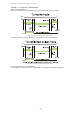
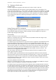
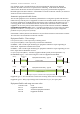
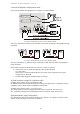
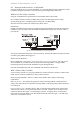
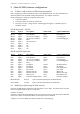
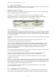
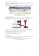
Table Of Contents
- 1 Introduction
- 2 Quick Guide to setting up S610S
- 3 Connecting an S610S Master Reader
- 3.1 Open the S610 reader case
- 3.2 S610S Master Reader 12V Power and Data connections
- 3.3 Extra settings required, made on the reader
- 3.4 Addressing an S610S master reader
- 3.5 S610S Connecting Master Reader Inputs
- 3.6 Monitoring Inputs for Cable Tampers
- 3.7 Using an external read head
- 3.8 S610S Lock and spare output relay connections
- 4 Connecting an S610S to an Exit Reader
- 5 Connecting an S610S to a DIU
- 6 AC2000 Devices Application tasks
- 7 Door Modes
- 8 Interlock
- 9 Other AC2000 software configurations
- 10 S610S onboard diagnostic mode
- 11 Appendix

S610S Manual - Hardware Installer Manual - Version 1.8
41
Connection Diagram for Equipment mode
Please note the S610SP Pico Reader does not support a second read head.
An example of S610S PCB connections used for Equipment Mode.
The relay connections, Normally Open or Normally closed will be specific to the equipment being
controlled.
An example of S610S PCB connections used for Equipment Mode.
The relay connections, e.g. Normally Open or Normally closed will be specific to the equipment
being controlled.
Note: Unless set otherwise the default relay states on a reader are Fail Safe.
• When power fails to a reader the Normally Open position becomes
in a Closed state.
When power is restored to the Reader the relay states become opposite to the legend
marked states on the PCB.
• S610S readers equipment feedback inputs are 0 and 2.
AC2000 software settings for equipment mode
WORKSTATION APPLICATION –HOLDER RECORD
No additional Personnel/Card Holder application settings are required for a card holder to enable
equipment using an S610S reader in Equipment Enable mode.
WORKSTATION APPLICATION – ACCESS LEVELS
Any S610S reader set to Enable Equipment mode must be placed into an Access Level.
Any card holder enabling controlled equipment must be a member of that Access Level.
Equipment Mode; Input configuration
Any Equipment Enable reader inputs used will be set to Normal. See Chapters 12 and 13 of this
manual. If not used inputs 0 and 2 must be disabled.