
User's Manual
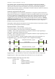
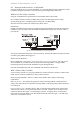
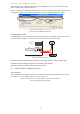
Table Of Contents
- 1 Introduction
- 2 Quick Guide to setting up S610S
- 3 Connecting an S610S Master Reader
- 3.1 Open the S610 reader case
- 3.2 S610S Master Reader 12V Power and Data connections
- 3.3 Extra settings required, made on the reader
- 3.4 Addressing an S610S master reader
- 3.5 S610S Connecting Master Reader Inputs
- 3.6 Monitoring Inputs for Cable Tampers
- 3.7 Using an external read head
- 3.8 S610S Lock and spare output relay connections
- 4 Connecting an S610S to an Exit Reader
- 5 Connecting an S610S to a DIU
- 6 AC2000 Devices Application tasks
- 7 Door Modes
- 8 Interlock
- 9 Other AC2000 software configurations
- 10 S610S onboard diagnostic mode
- 11 Appendix

S610S Manual - Hardware Installer Manual - Version 1.8
39
7.9 Equipment Enable mode
INTRODUCTION
A reader configured for equipment enable must not be used to control a door lock.
The S610S Equipment Enable door mode is used to independently control a maximum of two
external pieces of equipment e.g., check-in-desks. The control of the external equipment is provided
by the relay outputs on the S610S. One input on the S610S is available for each piece of equipment
under control to provide a feedback signal from the external equipment to the S610S. The S610S
can be configured to ignore the feedback signal during the enable period. Connecting a feedback
input is optional.
Setting Timing controls on equipment
By configuring suitable values for LockOpenTime and LockOpenTime2 equipment mode can be used
to provide either single pulse output to enable and disable external equipment or to provide a
latched output during the enable period.
Functionality
OUTPUT ACTION ON A VALID CARD SWIPE
Whenever a valid card swipe occurs on the master (slave) head the S610S will energise relay0
(relay1) for
LockOpenTime seconds.
FEEDBACK FROM EXTERNAL EQUIPMENT
If a feedback signal is provided from an output on the external equipment to the S600 this should be
connected to input0 (or input2 if the second relay is to be triggered) of the master reader. The
S610S will monitor this input during the
LockOpenTime period to ensure that the external equipment
has in fact been enabled. If a state change occurs on the relevant input, the S610S will enable the
amber LED on the master and slave head and maintain the energised state of relay0 (relay1) for
LockOpenTime2 seconds and transmits a Equipment Enabled signal to the host controller. The
S610S is now in the Equipment Enabled state.
If no state change is detected on the relevant input the S610S transmits an Equipment Enable
Failure signal to the host controller.
If no feedback signal is provided from the external equipment the S610S will enable the amber
LED on the master and slave head and maintain the energised state of relay0 (or relay1 if head two
is being used, see figure13.5a) for
LockOpenTime2 seconds and transmits a Equipment Enabled
signal to the host controller. If the S600E is not online to the host controller, all the above alarms
are stored as offline transactions.
S610S IN EQUIPMENT ENABLED STATE
Whenever a valid card swipe occurs on the read head one (or read head 2) the S600S will energise
relay0 (or relay1 if read head two is used) for
LockOpenTime seconds.
If a feedback signal is provided from the external equipment to the S610 this should be connected
to input0 (input2) of the S610S. The S610S will monitor this input during the
LockOpenTime period
to ensure that the external equipment has in fact been disabled. The S610S will disable the amber
LED on the master and slave head and transmit an Equipment Disabled signal to the host controller.
The S610S returns to the IDLE state. If no state change is detected on input0 (input2) the S610S
de-energises relay0 (relay1) after
LockOpenTime seconds and transmits an Equipment Disabled
Failure signal to the RTC and the S610S returns to the IDLE State.