
User's Manual
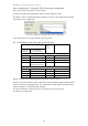
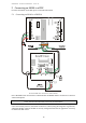
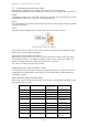
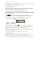

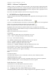
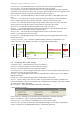

Table Of Contents
- 1 Introduction
- 2 Quick Guide to setting up S610S
- 3 Connecting an S610S Master Reader
- 3.1 Open the S610 reader case
- 3.2 S610S Master Reader 12V Power and Data connections
- 3.3 Extra settings required, made on the reader
- 3.4 Addressing an S610S master reader
- 3.5 S610S Connecting Master Reader Inputs
- 3.6 Monitoring Inputs for Cable Tampers
- 3.7 Using an external read head
- 3.8 S610S Lock and spare output relay connections
- 4 Connecting an S610S to an Exit Reader
- 5 Connecting an S610S to a DIU
- 6 AC2000 Devices Application tasks
- 7 Door Modes
- 8 Interlock
- 9 Other AC2000 software configurations
- 10 S610S onboard diagnostic mode
- 11 Appendix

S610S Manual - Hardware Installer Manual - Version 1.8
20
5.2 Connecting a powered lock to a DIU
The DIU has been designed to pass through either 24V or 12V for lock operation.
It is important to make the correct connections to enable the correct voltage for the connected lock.
DIU200
A DIU200 can support 12V or 24V locks. The correctly rated PSU (1.2A max) must be connected
to the DIU200
Lockin12V/24V connection, see the DIU module J2.
DIU210
The connection Supply 12V shown in the illustration provides a voltage supply used by any readers
connected to the board.
DIU220
The S610S can be configured only as an Exit reader when connected to a DIU220.
Lock and a choice of 12V or 24V lock power
Above, shows lock and a choice of 12V or 24V lock power connections (J2) on the DIU v3 PSB
and the larger (J2) on the DIU210 backplane.
SELECTING 12V OR 24V FOR LOCK SUPPLY
When making connections for Lock power, locate the connections as shown in the figure above;
work from the bottom up. The dotted lines indicate a choice of 12V or 24V power. Make your
selection according to the power rating of the door lock to be controlled.
J16 - J16 is an auxiliary 12V power take off point.
Using a Fail secure lock connected to a DIU
It is not possible to invert the DIU lock output using software settings. To enable fail secure lock
configuration it is recommended to connect the lock to the Holder output, and the Holder to the
Lock output, if present.
S610S with DIU Input connection table
When a DIU is present Inputs are not connected to the reader. Connect Inputs to the DIU, leaving
inputs on the Readers as spare.
Input # Input Description Normally Open /
Normally Closed
Connection
0
Door Position
Normally Closed J1 - CDIU - Door
1
Lock Status
Normally Closed J1 - CDIU - Lock
2
Request to Exit
Normally Open J1 - CDIU - REX
3
Break Glass
Normally Closed J2 - CDIU - BGlass
4
Fire
Normally Closed J2 - DIU200 or
J x – DIU210
5
Power Fail
N/A
+
J2 - CDIU - Fail
6
Battery Low
N/A
+
N/A
7
DIU Tamper
Normally Closed J2 - CDIU - Tamp
8,9,A,B (Master)
General Purpose
N/A
+
J6 - Master Reader
8-way JST
C.D,E,F (Exit)
General Purpose
N/A
+
J6 - Exit Reader
8-way JST