
User's Manual
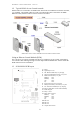
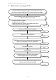

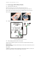
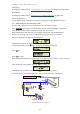
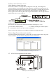
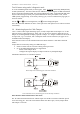
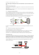
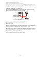
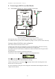
Table Of Contents
- 1 Introduction
- 2 Quick Guide to setting up S610S
- 3 Connecting an S610S Master Reader
- 3.1 Open the S610 reader case
- 3.2 S610S Master Reader 12V Power and Data connections
- 3.3 Extra settings required, made on the reader
- 3.4 Addressing an S610S master reader
- 3.5 S610S Connecting Master Reader Inputs
- 3.6 Monitoring Inputs for Cable Tampers
- 3.7 Using an external read head
- 3.8 S610S Lock and spare output relay connections
- 4 Connecting an S610S to an Exit Reader
- 5 Connecting an S610S to a DIU
- 6 AC2000 Devices Application tasks
- 7 Door Modes
- 8 Interlock
- 9 Other AC2000 software configurations
- 10 S610S onboard diagnostic mode
- 11 Appendix

S610S Manual - Hardware Installer Manual - Version 1.8
14
Test I/O states using reader’s diagnostic mode
To access S610S diagnostic mode, use the keypad. Enter followed by 0000 (Default)
or 9999 (old Default). After the reader has been added to a system using the AC2000 workstation
Devices application the default PIN will be downloaded to the reader. Default Reader PIN codes
may have been changed, consult your System Administrator If the pin number is lost, contact
CEM Systems, Support Dept. If incorrectly entering a pin, wait 5 seconds before trying again, to
allow for timeout.
Use the and to scroll through menu, use to select displayed option.
Select the TEST then INPUTS sub menu. Then open/close each input in turn in order to test their
functionality.
3.6 Monitoring Inputs for Cable Tampers
4 State - Used to enable input monitoring: Open, Closed, Tamper Short and Tamper Cut. If this
option is selected, cable tampering of ‘short’ and ‘cut’ will also be detected. Different types of
tamper are not distinguished, but simply reported as tamper. If a Tamper condition has occurred on
an input cable, e.g. a cut or short, then a subsequent alarm will not be detected, or appear on an
AC2000 Alarm Event Display.
THIS OPTION IS ONLY VALID IF RESISTORS HAVE BEEN ADDED TO THE INPUT SENSOR
WIRES.
Tamper detect is achieved by taking two additional steps:-
• Install a resistor network across the cabling at the input sensor.
• On an AC2000 Workstation Devices Application
- Enable 4-state tamper detect
- Configure the input to display a Tamper Alarm for any attempted tamper
INSERTING RESISTORS TO AN INPUT SENSOR
Normal Input sensor monitoring Open and Closed Conditions.
Sensor fitted with resistors, monitoring Open Closed and tamper conditions.
Note: Resistors must be fitted close to the sensor
The 1k resistor should be fitted in line with the input wire and the 2.2k resistor should be placed
across the wiring pair. This will ensure that the S610S will detect Open, Closed, Tamper Short
and Tamper Cut circuits.