
User's Manual
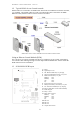
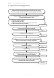

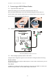
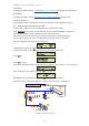
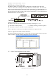
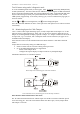
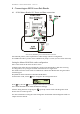
Table Of Contents
- 1 Introduction
- 2 Quick Guide to setting up S610S
- 3 Connecting an S610S Master Reader
- 3.1 Open the S610 reader case
- 3.2 S610S Master Reader 12V Power and Data connections
- 3.3 Extra settings required, made on the reader
- 3.4 Addressing an S610S master reader
- 3.5 S610S Connecting Master Reader Inputs
- 3.6 Monitoring Inputs for Cable Tampers
- 3.7 Using an external read head
- 3.8 S610S Lock and spare output relay connections
- 4 Connecting an S610S to an Exit Reader
- 5 Connecting an S610S to a DIU
- 6 AC2000 Devices Application tasks
- 7 Door Modes
- 8 Interlock
- 9 Other AC2000 software configurations
- 10 S610S onboard diagnostic mode
- 11 Appendix

S610S Manual - Hardware Installer Manual - Version 1.8
13
S610S Reader in Normal Operation
The Reader’s address is a four digit address, reading from left to right, the first digit is the
Controller address, the second digit is the NCN or Network Connection Node. The NCN is the
physical serial channel from the controller the reader is connected to. The third digit is the actual
reader’s address on that channel; each reader must be addressed uniquely, and the address is
directly applied to the reader using the reader’s keypad command menu. The last digit indicates a
Master Reader if 0 or an Exit reader if 1.
NORMAL OPERATION
The character after the time in the standard LCD message will change to O, C or F.
O – The reader is Online (normal) C – Coldstart (rebooting or Firmware update)
F – The Reader is Off line or has not received a configuration
If the
F is present the reader may not be added to AC2000 Devices application table.
Telnet or HyperTerm serial network controller
For further information about the state of a serial reader, use Telnet or Hyper Term to log on the
reader’s controller. Use the controller’s diagnostics to view reader states.
A screen shot of an S9064 controller Hyper Term session.
3.5 S610S Connecting Master Reader Inputs
S610S inputs, (when no DIU present).