
User's Manual
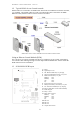
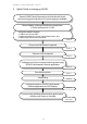

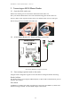
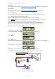
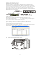
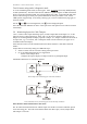
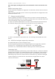
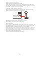
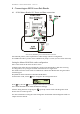
Table Of Contents
- 1 Introduction
- 2 Quick Guide to setting up S610S
- 3 Connecting an S610S Master Reader
- 3.1 Open the S610 reader case
- 3.2 S610S Master Reader 12V Power and Data connections
- 3.3 Extra settings required, made on the reader
- 3.4 Addressing an S610S master reader
- 3.5 S610S Connecting Master Reader Inputs
- 3.6 Monitoring Inputs for Cable Tampers
- 3.7 Using an external read head
- 3.8 S610S Lock and spare output relay connections
- 4 Connecting an S610S to an Exit Reader
- 5 Connecting an S610S to a DIU
- 6 AC2000 Devices Application tasks
- 7 Door Modes
- 8 Interlock
- 9 Other AC2000 software configurations
- 10 S610S onboard diagnostic mode
- 11 Appendix

S610S Manual - Hardware Installer Manual - Version 1.8
11
3
3
C
C
o
o
n
n
n
n
e
e
c
c
t
t
i
i
n
n
g
g
a
a
n
n
S
S
6
6
1
1
0
0
S
S
M
M
a
a
s
s
t
t
e
e
r
r
R
R
e
e
a
a
d
d
e
e
r
r
3.1 Open the S610 reader case
Remove the retaining screw located on the underneath of the reader case.
Place your thumb underneath the screw hole and lift the lining plate off the reader case.
X4 screw holes will be exposed. Remove the screws and the reader case will come apart.
Reverse the process to re-assemble the reader case.
3.2 S610S Master Reader 12V Power and Data connections
Shows S610S, RS485 data and power connections.
3.3 Extra settings required, made on the reader
Using the reader’s diagnostic keypad a serial reader must be configured with the following:-
Reader Address
The Reader will have to be uniquely addressed (0-F), no other reader on the channel or port can
share the same address.
Door Mode
In addition to an address, the reader will need to have the correct Door Mode set, and the read
head and card type enabled. See Door Mode chapter in this manual.