
User's Manual
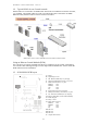
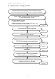

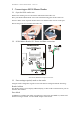
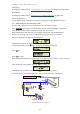
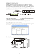
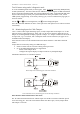
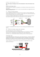
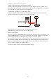
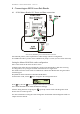
Table Of Contents
- 1 Introduction
- 2 Quick Guide to setting up S610S
- 3 Connecting an S610S Master Reader
- 3.1 Open the S610 reader case
- 3.2 S610S Master Reader 12V Power and Data connections
- 3.3 Extra settings required, made on the reader
- 3.4 Addressing an S610S master reader
- 3.5 S610S Connecting Master Reader Inputs
- 3.6 Monitoring Inputs for Cable Tampers
- 3.7 Using an external read head
- 3.8 S610S Lock and spare output relay connections
- 4 Connecting an S610S to an Exit Reader
- 5 Connecting an S610S to a DIU
- 6 AC2000 Devices Application tasks
- 7 Door Modes
- 8 Interlock
- 9 Other AC2000 software configurations
- 10 S610S onboard diagnostic mode
- 11 Appendix

S610S Manual - Hardware Installer Manual - Version 1.8
8
1.2 Typical S610S Access Control network
S610S readers are connected to an RS485 serial chain from an AC2000 serial network controller,
e.g. an S9064. Also S610S readers are used as an Exit Reader when connected to an S600E
Ethernet reader; Ethernet readers cannot be used as exit readers.
S610S readers can be used on an RS485 serial chain as Master and Exit readers.
Using an Ethernet Control Module (ECM)
If it is necessary to connect an S610S serial device to an Ethernet access control system (RTC)
use an ECM. This CEM signal bridge converts duplex Ethernet RS485 data. Please consult the
ECM manual for more information.
1.3 S610S/S600S PCB layout
C9 Buzzer
D9 Light/Tamper sensor
J2 H0 - Master Read Head, 8-way JST plug
J3 Smart card or Biometric Interface, 6-way JST
J5 RS485 to Exit Reader, 4-way JST
RS485A, Pin1
RS485B, Pin 2
12V, Pin 3
0V, Pin 4
J6 Input terminals 0-3, 8-way JST plug
J7 Backup Power Battery connection, 2-way JST
J9 H1 – Exit/Slave Read Head, 8-way JST plug
J10 Ethernet, RJ45 (Not used on S610S or S600S)
J11 Reader Keypad
J12 Relays 1 and 2
J15 Master Data Connector
RS485A, Pin1
RS485B, Pin 2
12V, Pin 3
0V, Pin 4
LK4 Not used
LK5 Not used
LK7 Not used
U7 Compact Flash locator