
User's Manual
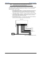
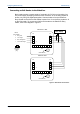

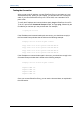
Table Of Contents
- Important Safety Information
- Introduction
- EtherProx Entry Installation
- Configuring the EtherProx Entry
- Administering the EtherProx Entry
- Diagnostics
- Glossary

Configuring EtherProx Entry EtherProx Entry
Connecting an Exit Reader to the EtherProx
Both readers require a power supply of nominally 12V DC this can be taken from
one power supply by tapping off the Phoenix connector J3 on the Entry reader as
shown or by using two separate supplies. Communications from the EtherProx
Entry Reader to the InfoProx Exit reader is taken from J3 on the Entry reader to J3
on the Exit reader. To connect an InfoProx Exit reader to the EtherProx Entry
reader, refer to the diagram in Figure 6.
B
+
-
A
6 RX- green
2 TX- orange
3 RX+ white/green
1 TX+ white/orange
J5
J2
Sound Device
J3
1
RJ-45
pin number
1
Front view
of RJ45
plug
J5
J2
Sound Device
J3
1
EtherProx Exit
TM
InfoProx Exit
TM
A
B
+
-
Nominal 12V
Power Supply
Figure 6: Exit Reader Connections
Page 16 Software House