
User's Manual
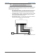
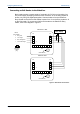

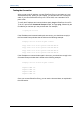
Table Of Contents
- Important Safety Information
- Introduction
- EtherProx Entry Installation
- Configuring the EtherProx Entry
- Administering the EtherProx Entry
- Diagnostics
- Glossary

EtherProx Entry EtherProx Entry Installation
Note On the back of the unit, pin 1 is at the right end of the connector, as
shown in Figure 4. Pin 10 is Common; Pin 9 is N/O.
The diagram in Figure 5 illustrates typical connections to a door. The power supply
must have sufficient capacity to operate the door strike. You can connect three
optional switches, which include:
· Door state monitor switch – a normally closed switch whose contacts
are closed when the door is closed; EtherProx Entry uses the door
state monitor switch to generate the door held and door open alarms
· Lock status switch - if present, a normally closed switch that is usually
part of the door strike assembly. If lock status monitoring is enabled,
the lock status switch must be connected
· Exit pushbutton switch – a normally opened switch that is used if the
door lock must be released to leave the secured area
C NO J2
12345678910
InfoProx Entry
Door State
Monitor (NC)
(Optional)
Lock Status
Switch (NC)
(Optional)
Exit Pushbutton (NO)
Optional
Door
Strike
Door Strike
Power Supply
Figure 5: Typical Connections to a Door
Software House Page 15