
User's Manual
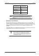
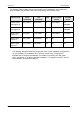
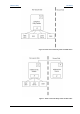
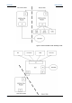
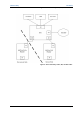

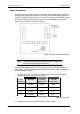
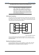
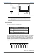
Table Of Contents
- Important Safety Information
- Introduction
- EtherProx Entry Installation
- Configuring the EtherProx Entry
- Administering the EtherProx Entry
- Diagnostics
- Glossary

Configuring EtherProx Entry EtherProx Entry
6 RX- green
2 TX- orange
3 RX+ white/green
1 TX+ white/orange
J5
J2
Sound Device
J3
1
RJ-45
pin number
1
Front view
of RJ45
plug
Figure 3:EtherProx Entry Connection
Note The wire colors in Figure 3 may not always correspond with the
particular cable you are using. For example, the orange conductor may
be orange/white.
Door Connections
The door connections for normal door mode:
INPUT DOOR CONNECTION
Input 0 Monitors door position (normally closed)
Input 1 Monitors lock status (normally closed)
Input 2 Exit push button (normally open)
The four inputs and the relay output for the reader are located in a 10-pin Phoenix
Contact connector J2, as shown in Figure 4. The door control unit has a single-
pole relay with a set of dry contacts rated at five amps at 30 VDC maximum. The
common connection is available on pin 10; the normally opened connection is
available on pin 9 of J2. For normal door mode, the relay is reserved for door
strike control. The relay operates when a valid card is presented. You can
configure the relay as Powered to Unlock or Powered to Secure.
10 9 8 7J26 5 4 3 2 1
Relay
Contacts
Input 3
(unused)
Input 2 Input 1 Input 0
Figure 4: Inputs and Outputs on J2
Page 14 Software House