
User's Manual
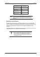
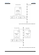
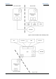
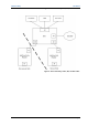

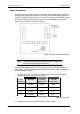
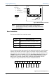
Table Of Contents
- Important Safety Information
- Introduction
- EtherProx Entry Installation
- Configuring the EtherProx Entry
- Administering the EtherProx Entry
- Diagnostics
- Glossary

EtherProx Entry EtherProx Entry Installation
3. If the result is greater than 7.0 volts, the wiring is adequate. If not, use heavier
(lower gauge) wire or a power supply with a higher voltage output.
Example: If you use a 22AWG wire with a 12-volt power supply 300 feet
away from the readers, the voltage drops to 7.2 volts at the
reader. Using the Table 1: Voltage Table to calculate the
voltage, multiply 3 (300 ft) times the 1.6V drop equals a -4.8
drop for the 300 ft. span. Subtract 4.8 from the 12V supply,
which equals 7.2. A voltage of 7.2 at the readers is sufficient
power to operate the readers above the 7V minimum required.
In this example, the total distance from the power source and
the exit cannot be more than 300 ft.
Exit Reader Connections
The InfoProx exit reader is connected to the entry reader through a two-pair cable,
providing power and communications. The connection is from connector J3 on the
entry reader to connector J3 on the exit reader, and is connected at both ends with
a four-pin Phoenix Contact socket (see Figure 2).
J3
InfoProx Exit
Ether
Prox Entry
J3
A
B
+
-
A
B
+
-
Figure 2: Exit Reader Connections
The recommended interconnecting cable is Belden 8723 or equivalent. It is not
necessary to connect the drain wires in the cable. You can cut the drain wires off
flush with the jacket.
EtherProx Entry Ethernet Connection
Connect the Ethernet cable to J5 using a Category 5 or better cable. Terminate
the keypad end with a 4-pin Phoenix connector. Connect the other end of the
Ethernet cable to an RJ-45 female connector (see Figure 4).
Software House Page 13