
Technical data


CHALLENGE/Onyx Diagnostic Road Map 4-3
stopped, a “Blower Failure” message is displayed. All three conditions result in a system
shutdown.
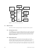
4.2.3 Power-On, Boot, and Reset Sequences
The System Controller plays an active role in the power-on, boot, and reset processes. The
power-on process begins when the System Controller enables the OLS outputs, supplying
48 volts to the midplane. Next, the blower(s) are turned on and their speed monitored.
Then the System Controller sequentially turns on a series of power-enable lines (PENA
through PENE). As each system component is brought up, the System Controller tests for
a valid power-OK signal (POKA through POKE), which indicates that the voltages just
enabled are within the specified range. If the power-OK signal remains high, the System
Controller asserts the next power-enable line in the series. If a power-OK signal is bad (goes
low), the System Controller will halt the power-on sequence. When the power-on sequence
is complete, the System Controller deasserts power-clear (PCLR) and system clear (SCLR).
See Chapter 3, “Power Subsystem” for additional information.
The PCLR/SCLR signals cause all of the system’s processors to reset, beginning the first
step in the bootmaster arbitration process (see Chapter 5, “PROM Monitor”). The System
Controller then polls each of the CPU boards over the Polled Serial bus. The first CPU
polled is the board with the lowest address. If that CPU has successfully passed its self-test,
it notifies the System Controller that it is becoming the bootmaster, and sends interrupts to
any other CPUs. If the first CPU failed its self-test, the System Controller will increment the
CPU address by one and offer the bootmaster role to the next CPU. The first CPU board to
successfully complete its self-test and respond to the poll becomes the bootmaster. The
bootmaster CPU takes control of the boot process and uses the serial link to the System
Controller to transmit status and error messages.
When the operator requests a reset using the status panel, the System Controller asserts the
SCLR line, as it does following the power-on sequence. The processors are reset and the
boot arbitration and power-on test process starts over. However, the 48 VDC is never
removed from the midplane.
Note: Before requesting a system reset, terminate all processes and run an init 0 to halt
IRIX gracefully.
4.2.4 Monitoring Normal System Operation
During normal system operation, the System Controller periodically monitors the system
backplane voltages, the backplane clock, the air temperature in the cabinet, and the blower
speed. The Power Fault Warning (PFW) signals, from the offline switchers, are also
monitored in order to allow the system to gracefully power-off in the event of an
impending loss of power. Status messages from the bootmaster CPU are transmitted to the
System Controller and are available at the controller’s display.
The System Controller will issue and display a warning if an abnormal condition is
detected but does not warrant a system shutdown. This condition can be detected by either
the System Controller’s sensors or by the bootmaster CPU. In these cases, the warning is
issued only to inform the user.