
Technical data


4-2 Using the System Controller
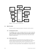
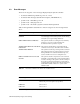
Figure 4-1 System Controller Input/Output Signals
4.2 Basic Functions
This section provides a step-by-step description of the System Controller operation.
4.2.1 Overtemperature Sensor
The OVERTEMP_L line is located on the midplane. When the sensor detects a temperature
of 70°C, this DOT-OR line is pulled low to inform the System Controller of the fault. The
System Controller then records the fault in the history fail, deasserts PENx, and asserts
RI_H to remove all power from the system. Note that the key switch position must be
changed to restart the system.
4.2.2 Blower Speed Control
A linear temperature sensor is mounted near the analog-to-digital convertor. The
tachometer output of the system’s blower(s) is monitored by the System Controller. The
tachometer output is used by the System Controller to control the blower speed.
An inlet temperature greater than 50°C generates an “Ambient Over Temp” message on the
status panel. Low blower speed results in a “Blower RPM Failure” message. If a blower is
Backplane
Monitored
Levels
48 V, 12 V, 5V ,
1.5 V, −5.2 V, 12 V,
BP Clock
CPU_COMMUN.
SERIAL_ADDRx
SERIAL_BRDOUT
SERIAL_BRDIN
SERIAL_CLK
CPU Control
PCLR_OD
SCLR_OD
BPNMI_L
OLS
Rlx_H
48 V
PFWx_L
Status Panel
Keypad/Keyswitch
LCD Display
System Controller
Firmware−EPROM
Real−time Clock
NVRAM
Battery Backup
Secondary
Serial Ports.
TXD, RXD, RTS,
CTS, DCD, DTR
BLOx_MTR
BLOx_TACH
Power Control
PENx, POKx,
Blower(s)
Temperature Sensors
Board/Chassis Sensors
Inlet Temp Sensor
V5_AUX
V12+
VEE_DIS