
Technical data


CHALLENGE/Onyx Diagnostic Road Map 4-1
Chapter 4
4. Using the System Controller
4.1 Overview
The Everest System Controller is a microprocessor with a battery-backed clock and RAM.
The System Controller performs three basic functions:
• The System Controller manages the system’s power-on, power-off, and bootmaster
arbitration processes. It also displays a running account of the status of the boot
procedure and notifies the bootmaster CPU when a system event, such as power off, is
initiated.
• When operating conditions are within normal limits, the System Controller is a
passive monitor. The only active role the System Controller plays is in monitoring the
cabinet temperature and adjusting the blower speed. Its front panel LCD offers a
running CPU activity graph that shows the level of each processor’s activity.
Previously logged errors are not available on the status panel at boot time, but are
transferred into /usr/adm/SYSLOG and a new log started.
• The System Controller can also act independently to shut down the system when it
detects a threatening condition. Or it can adjust electro mechanical parameters (such
as blower speed) to compensate for external change. The Manager position, on the
key switch, provides menus used to probe for system error information.
The system serial number and event history log are stored in non-volatile RAM. The RAM,
along with its battery backup and the System Controller’s real-time clock, is packaged in a
single, 24-pin DIP IC. The IC is socketed on the Ebus power board at location K3C3.
If the Ebus power board must be replaced, the RAM IC must be removed and installed on
the new Ebus board. If the IC is not swapped, the system serial number must be written
onto the new IC using the PROM Monitor serial command. The SGI part number of the
RAM IC is 9018383. The manufacturer’s part numbers are DS12887 and BQ3287.
Caution: Observe proper electrostatic discharge (ESD) precautions when handling this
device.
This chapter describes the operation of the System Controller during the power on, power
off, and boot sequences, as well as during both normal system operation and during an
emergency shutdown. Explanations of the possible error messages are presented in Section
4.3, “Error Messages.”
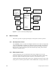
Figure 4-1 illustrates the system components monitored and controlled by the System
Controller.