
Technical data

CHALLENGE/Onyx Diagnostic Road Map 3-15
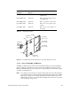
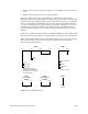
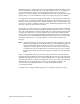
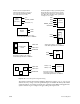
all OR-tied together, so a failure sensed by any of the POK lines indicates the failing voltage
but cannot isolate the specific FRU. Also, in systems with more than one of each type of
power board, identical voltages are ganged together. Finally, there are secondary
regulators; one on the backplane, two on the IO4 board, one each on the MC3 and VCAM
boards, and one on each of the FMezz boards, whose output voltages are only POKed.
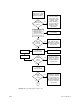
A voltage fault is isolated by inspecting the fault LEDs on all of the suspect boards before
powering down or resetting the system (refer to the tables in the following section for the
LED error codes). Check the system for a lit POKx LED when either a voltage fault message
(such as 5 V low fault) or a POK error message (such as POKx bad) is displayed. The points
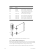
where the voltages are monitored are shown in .
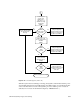
If a CPU, blower, voltage regulator, or power brick fails, the System Controller will disable
the bricks but will leave 48 volts at the midplane/backplane and the V5_AUX on. V5_AUX
allows all of the fault LEDs to remain lit and provides power to the Status Panel and System
Controller. If a shutdown has occurred, check the error message that is displayed and
visually inspect the corresponding fault LEDs throughout the system to isolate the fault.
See Section 3.2, “Power Fault Indicator Descriptions and Locations” for the locations of the
fault LEDs, and Section 3.3, “Power-On Sequence,” for the System Controller error
messages.
Note: Check the Status Panel for error messages and inspect the cardcage(s) for lit fault
LEDs before restarting the system. Repeated power cycling during fault diagnosis
will eventually fill the System Controller event history log and overwrite the
original error message. The bootmaster CPU can save the contents of the System
Controller history log in/usr/adm/SYSLOG only after the boot process is complete.
If the fault prevents the system from booting, there will be no record of the fault in
UNIX.
If any over-temperature fault occurs, the entire system shuts down. Isolate the fault by
restarting the system with the key switch and checking the error message on the front panel
display. If the temperature sensors are not given sufficient time to cool below the trip point,
the system will continue to shut down. Temperature sensors are located on the CPU (IP19
and IP21), MC3, 512S, and IO4 boards, as well as on the backplane/midplane. See
Section 4.2.5.1, “Overtemperature Faults” for additional information about
over-temperature faults.
See Figure 3-15 for a diagram illustrating the power subsystem voltage monitoring.