
Technical data

CHALLENGE/Onyx Diagnostic Road Map 3-13
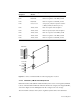
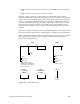
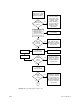
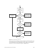
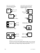
Figure 3-12 Power-On Sequence (Part 2 of 2)
When the system has successfully powered up, the System Controller deasserts the power
clear (PCLR) and system clear (SCLR) signals to the address ASIC on each CPU board. The
cache controllers then reset each of the system’s processors and the power-on tests are
started. (Power-on tests are described in Chapter 5, “PROM Monitor.”)
Looks for good
system clock.
Enables 5.0 V
and 12V for 1st
SCSIBox (housing
system disk).
(PENC)
POKC
signal received.
Clock OK
Yes
Power−on halted, failing
voltage displayed by
System Controller. Check
voltages on 512S power
board in 1st SCSIBox.
No
POKC
A
System shutdown initiated.
System Controller displays
"No System Clock"
message
No
Clock
Enables 5.0 V and
12 V for optional 2nd
SCSIBox
(PEND)
POKD
signal
received
Yes
Power−on halted, failing
voltage displayed by
System Controller. Check
voltages on 512S power
board in 2nd SCSIBox.
No
Enables 5.0 V and
12 V for external
SCSI drive boxes.
(PENE)
POKE
signal
received
Yes
Power−on halted, failing
voltage displayed by
System Controller. Check
voltages at external
drive box.
Power−on Sequence Complete