
Technical data

3-12 Power Subsystem
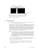
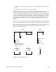
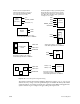
Figure 3-11 Power-On Sequence (Part 1 of 2)
Main power switch on.
Status panel key switch
in ON position. 48 VDC
applied to backplane.
Green
Status Panel
LED lit
No 48 V from OLSs.
Check key switch,
status panel, cable
to backplane, System
Controller, cable
between backplanes.
Check incoming AC,
backplane voltage,
OLS power, LEDs,
OLS cabling.
No
48 V present at
midplane/backplane.
System Controller
generates 5V_AUX
line. Blower(s) Run
System
Controller
comes up
Blower(s) Off. Check
fuses/cabling.
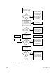
No
Check V5_AUX, V12+,
DIS_VEE. No signal −
Faulty System Controller
Check OLS amber LEDs.
DC good if lit.
Enables 5.0 V and
12 V bricks for
cardcages (PENA)
Start SYS_CLOCK
Enables PENA
Enables PENA
POKA
signal
received
Yes
Power−on halted,
"POKA Fault" displayed
by System Controller.
Check all fault LEDs
on power boards
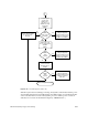
Yes
Enables 1.5 V and
3.3 V for
cardcages (PENB)
Yes
POKB
signal
received
Yes
Power−on halted.
"POKA Fault" displayed
by System Controller. If
1.5V, 3.3V failed, check
secondary regulators on
IO4, MC3 and VCAM. If
3.3V failed, check power
brick on IP19
No
A