
Technical data

CHALLENGE/Onyx Diagnostic Road Map 3-11
• PEND: controls 5 and 12 volts for the optional, second SCSIBox (rackmount systems
only)
• PENE: controls 5 and 12 volts for any external cabinets
Each time a signal is asserted, a corresponding power-OK (POKx) signal is tested,
indicating to the System Controller that the voltage levels are correct. If any voltage-enable
line does not generate an OK signal, the System Controller will stop the power-on sequence
at the point of the failure. The POKx signals are continually monitored during and after
power up. Any POKx signal going low indicates a power-fail condition at one or more of
the system power supplies/regulators. A low POKx signal (except POKE) causes the
System Controller to display a “Power Fault” message and begin the system power-off
sequence.
In the case of a fault following the assertion of PENE, the POKE line is asserted 30 seconds
later. The system treats this signal as a warning and does not begin the power-off sequence.
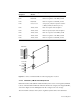
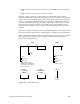
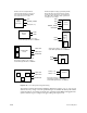
Figure 3-10 illustrates the relationship of the POKx signals to the various system voltages
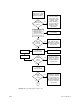
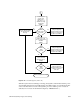
and components. The system power-on sequence is illustrated by the flowchart in
Figure 3-11 through Figure 3-12.
Figure 3-10 Power OK (POKx) Signals
5 V 12 V −5.2 V −12 V 1.5 V 3.3 V
IP19
505, 505x2
512, 512S
512
512S
VCAM
IO4
VCAM
Mezz Cards
Ebus (Sys Cntlr)
GE10
(if Onyx system)
IP19
* Debug a POKA error by
disabling the VCAM and then
the 512 boards to isolate the
origin of fthe fault.
POKA POKB
512S
POKC
(1st rackmount
SCSIBox)
5 V 12 V
512S
POKD
(2nd rackmount
SCSIBox)
5 V 12 V
POKE
External
Cabinets