
Technical data

3-10 Power Subsystem
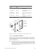
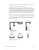
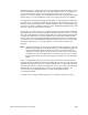
Figure 3-9 SCSIBox Fault Indicators
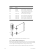
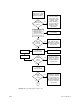
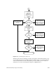
3.3 Power-On Sequence
Note: The power switch (main circuit breaker), located in the lower right corner of the
front of the system cabinet, must be turned on.
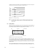
Turning the System Controller key switch to the On or Manager position enables the OLSs
to output 48 volts to the midplane/backplane. The green power-on LED, above the front
panel display, lights to indicate that voltage is present at the midplane/backplane. The
step-down regulator on the System Controller power board converts the 48 volts to 5.0
volts (V5_AUX) for use by the System Controller, power brick control circuits, and LEDs.
As the System Controller powers up and begins its initialization, the amber fault LED
above the display lights. When the System Controller successfully initializes and the
power-on tests are complete, the amber fault LED goes out.
Note: If the system will not power up (green front panel LED not lit), first check the LEDs
on each of the offline switchers. If the OLSs do not indicate a fault, verify that there
are 48 volts at the backplane near the power-on LED. If the backplane voltage is
correct, but the System Controller has not initiated the power sequencing, first
check the display for an error message, then check the System Controller board
and verify that the 5.0 V VS_AUX line from the System Controller is supplying
power to the power bricks.
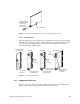
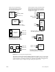
The System Controller then manages the power sequencing for the rest of the system. A
series of power-enable (PENx TTL_H) signals are asserted in the following sequence:
• PENA: controls +5.0, -5.2 and +/-12 volts
• PENB: controls 1.5, 1.6 (System Controller termination voltage), and 3.3 volts
• PENC: controls 5 and 12 volts for the first SCSIBox housing the system disk
(rackmount systems only)
Power fault LEDs
Drive sled connector
SCSIBox access door