
Technical data
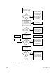
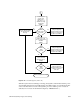

CHALLENGE/Onyx Diagnostic Road Map 3-7
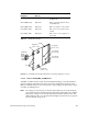
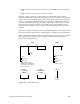
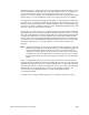
Figure 3-5 First IO4 Board/VCAM Fault Indicator and Voltage Regulator Locations
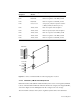
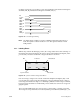
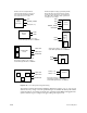
3.2.2.4 Remote VCAM (RMT_VCAM) Board
The RMT_VCAM board has a bank of nine fault LEDs that flag power faults stemming
from the Cardcage 3 backplane, the System Controller, and the three regulators on the
RMT_VCAM itself. There are also six test points corresponding to the monitored voltages
(see Table 3-3 and Figure 3-6).
Note: The voltage levels of the three on-board voltage regulators are monitored by two
sets of LEDs: the three red LEDs and the bottom three amber LEDs. The red LEDs
light when a voltage error is sensed and remain lit until the system is reset. The
amber LEDs provide a “hot” measurement and light only when an error is present
in the monitored voltage levels.
LED Reference
Designation
Color / Meaning
When Lit
Description
M2P6 (POKB_FAIL) Red/Fault Bad 1.5 V regulator A (near top) on
the IO4 board
M1P6 (POKB_FAIL) Red/Fault Bad 1.5 V regulator B (near bottom)
on the IO4 board
M0P6 (POKB_FAIL) Red/Fault Bad 1.5 V regulator on the VCAM
L9P6 (POKA_FAIL) Red/Fault Bad -12 V to -5.2 V regulator on the
VCAM
L8P6 (POKA_FAIL) Red/Fault Bad +12.0 V to -12.0 V regulator on
the VCAM
Table 3-2 IO4 Board Fault LEDs
Fault LEDs
VCAM
M2P6
M1P6
M0P6
L9P6
L8P6
IO4
Regulator A
(+5V to +1.5V)
Regulator B
(+5V to +1.5V)
1.5 regulator
(+5V to +1.5V)
-12V regulator
(+12V to -12V)
-12V regulator
(+12V to -5.2V)
Fuses