
Technical data

3-6 Power Subsystem
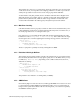
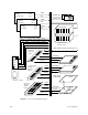
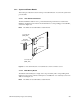
Figure 3-4 MC3 Board Fault Indicator and Power Brick Locations
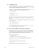
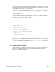
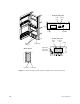
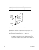
3.2.2.3 IO4/VCAM Board
The IO4 board has a single bank of five LEDs and two secondary regulators. These
regulators convert +5 volts to +1.5 volts (see Table 3-2 and Figure 3-5). The IO4 also has
three replaceable fuses, as shown in Figure 3-5.
The VCAM board three secondary regulators: +1.5, -12, and -5.2 volts.
Note: All LEDs are red and indicate a fault when lit. The bottom three LEDs provide
power fault indications for the attached VMEbus Channel Adapter Module
(VCAM). The VCAM fault LEDs are mounted on the IO4 board because the
dimensions of the VCAM would make on-board LEDs extremely difficult to read.
These LEDs are unlit when no VCAM is installed.
LED Reference
Designation
Color / Meaning
When Lit
Description
N8P2 (POKB_FAIL) Red/Fault Bad 3.3 V power brick
B4P2 (POKA_FAIL) Red/Fault Bad 5.0 V power brick
Table 3-1 MC3 Board Fault LEDs
3.3V Fail LED
(POKB_FAIL)
(not present in
this version)
Provision for
3.3V Power
Brick (not
present in
this version)
5.0V Power
Brick
5.0V Fail LED
(POKB_FAIL)