
Technical data

CHALLENGE/Onyx Diagnostic Road Map 3-3
When the system is turned on, the power subsystem goes through a series of voltage checks
before the boot process is allowed to start. Power is applied to the various system
components in the following order: +/-5 V and +/-12 V power bricks (power for the SCSI
drives in the deskside systems), 1.5 V and 3.3 V power bricks, 5 V and 12 V power bricks
(power for the first internal SCSIBox in the rackmount systems), and 5 V and 12 V for
external SCSI. This power sequencing is designed to prevent component damage due to
incorrect or missing voltages, and to avoid placing a large transient demand on the voltage
source.
There are only three diagnostic tools at this point in the system’s start-up sequence: the red
fault LEDs on each circuit board, the AC voltage input and DC voltage output LEDs on
each OLS, and the System Controller. To effectively use these indicators to troubleshoot a
system fault, refer to the fault indicator descriptions and the power-up sequence described
in the following sections.
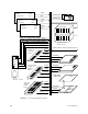
3.2 Power Fault Indicator Descriptions and Locations
This section describes the power fault indicators found on each system and power board,
on each OLS, on the SCSIBox backplane, and on the system Status Panel. The locations of
the power fault indicators, the power bricks, the removable fuses, and the secondary
regulators (where applicable) are also shown.
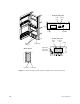
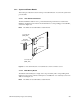
3.2.1 System Controller and Offline Switchers (OLSs)
Two LEDs are located above the System Controller function buttons (see Figure 3-2). The
green power-on LED lights to indicate that 48 volts is present at the system
midplane/backplane, and remains lit as long as 48 volts are present. The amber fault LED
lights briefly during the power-up sequence, but should go out when the power-on tests
are complete.
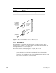
Each OLS also has a green and an amber LED. The amber LED lights to indicate that the
AC input voltage level is within acceptable levels. The green LED lights to indicate that the
DC output voltage levels are within acceptable levels. Both LEDs should remain lit during
normal system operation.