
Technical data

CHALLENGE/Onyx Diagnostic Road Map 2-35
2.6 Error Message Syntax
Everest hardware errors are displayed following IRIX kernel panics, in the IDE stand-alone
diagnostics, and in some of the PROM-based power-on tests. The display format of the
error messages is referred to as the HARDWARE ERROR STATE, and is defined as follows:
• The only bits displayed are those indicating an error has been detected. Normal bits
are not displayed.
• The display walks through all the boards in the system and through every ASIC on
each board.
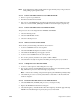
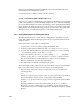
• A HARDWARE ERROR STATE display consists of the banner line HARDWARE ERROR
STATE:
followed by indented lines prefixed by a plus (+) sign. Line indentation, from
left to right, indicates the board, the ASIC, the register, and the bit. For example:.
HARDWARE STATE:
+IP19 in slot 1 (CPU Board)
+CC in IP19 slot 1, CPU 0 (ASIC on CPU Board)
+CC ERTOIP Register: 0xffff (Register in the CC and its hex value)
+Parity Error on TAG RAM Data (Bit in the register that is set)
• Each error register’s value is shown in hexadecimal, followed by a line for each bit set.
• Each board identifies its location with its board slot number. Each ASIC identifies its
location with some address information: a CC by the CPU it is associated with, the
EPC, F chip, or S chip by its Ibus adapter number.
Note: The F chip also identifies the ASIC that is at the other end of its flat cable.
• The decimal bit number precedes the name of each error bit.
• Some registers have multibit values and are displayed in hexadecimal rather than as
bits.
The kernel will panic in response to many possible hardware errors. The HARDWARE
ERROR STATE messages allow you to trace the error back to the ASIC that originally
detected the fault, thereby identifying the FRU to be replaced. Relate the error message to
a block diagram of the system, and walk the propagated errors backwards to determine
where the fault originated.
As an example, assume that a driver, executing on an IP19 CPU, attempts to read a control
register on a VMEbus device. If the controller fails to respond, the VMEbus will time-out.
The time-out causes the VMECC to record VME Bus Error on PIO Read. The VMECC will
return an error message to the F ASIC. From the F ASIC, the error passes through the IA
ASIC, the A ASIC, and the CC chip and finally reaches the CPU as a bus error. Each of the
ASICs in this sequence may record the error. The kernel panics and dumps all of the set
error register bits. You must understand the possible error propagation paths throughout
the machine to distinguish the secondary, propagated errors from the origin of the fault.