
Technical data


2-24 Diagnostic Procedures
+ 7 : Error in SCSI Data DMA channel 1 6 detected error from SCSI
+ 8 : Error in SCSI Data DMA channel 2 6 detected error from SCSI
+ 9 : PIO Read Error in SCSI 0 6 detected error from SCSI
+ 10: PIO Read Error in SCSI 1 6 detected error from SCSI
+ 11: PIO Read Error in SCSI 2 6 detected error from SCSI
+ 12: PIO Write data Overrun due to PIO FIFO Full
5 S1 internal error
+ 13: Missing Write data during PIO write
5 S1 detected error on IBus
+ 14: PIO with an invalid address 5 S1 detected error on IBus
+ 15: PIO Drop mode active 5 S1 detected error on IBus
+ S1 Ibus error Register: 0x1fffffff
+ 1: Error on Incoming Data to S1 - multiple occurances
5 S1 detected error on IBus
+ 2: Error on Incoming command to S1 - multiple occurances
5 S1 detected error on IBus
+ 3: Error on Outgoing data from S1 - multiple occurances
5 S1 detected error on IBus
+ 4: Error on Outgoing command from S1 - multiple occurances
5 S1 detected error on IBus
+ 5: Error in DMA translation - multiple occurances
5 S1 detected error on IBus
+ 6: Error in Channel 0 - multiple occurances
+ 7: Error in Channel 1 - multiple occurances
+ 8: Error in Channel 2 - multiple occurances
+ 9: Surprising DMA Read/Ibus Grant - multiple occurances
5 S1 detected error on IBus
+ 10: PIO Read response Error - multiple occurances
5 IA detected error in data
from S1
+ 11: PIO Write request Error - multiple occurances
5 S1 detected error on IBus
+ 12: DMA Read response Error - multiple occurances
5 S1 detected error on IBus
+ 13: Interrupt Error - multiple occurances
5 IA detected error
+ IBus Opcode+Address: 0xbfe0 5 holds the S1 emitted IBus
operation where a Parity
error was reported by IA
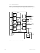
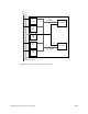
2.4.1.4 MC3 Memory Board
Figure 2-8 is a functional block diagram of the MC3 board showing the error detection.
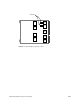
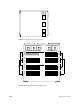
Figure 2-9 shows the physical layout of the board and the locations of the error detection
logic. The error messages are listed in the following section.