
Technical data

CHALLENGE/Onyx Diagnostic Road Map 2-11
Note: The numbers following each error message correspond to the interface where the
error detection logic is located. These registers are duplicated for each installed
processor.
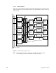
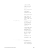
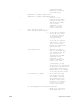
2.4.1.2 IP21 CPU Board
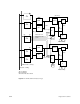
Figure 2-4 is a functional block diagram of the IP21 board with the error detection points
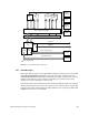
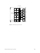
called out. Figure 2-5 shows the physical layout of the board and the locations of the error
detection logic.