
Technical data

CHALLENGE/Onyx Diagnostic Road Map 2-7
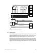
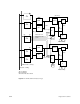
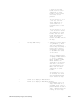
Figure 2-1 Everest Bus Parity Checkpoints
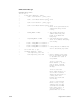
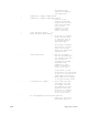
2.4.1 Error Messages
When the hardware detects an error, IRIX and the diagnostics display it in a format called
the HARDWARE ERROR STATE display. This section provides a complete list of the
HARDWARE ERROR STATE messages, arranged by board type. Each message contains a
number representing the location of the error-checking logic (usually a bus-to-ASIC
interface), as well as a description of the error bit.
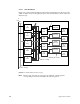
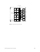
Each circuit board is represented both by a functional block diagram and by a board layout
showing the physical locations of the error detection logic. Following the two figures that
support each board is a table listing the possible hardware errors, along with a number that
identifies where the error was detected.
MC3
1
MC3
2
IP19/IP21
2
IP19/IP21
1 (Master
CPU)
System
Controller
Cooling
Fans
Offline
Switchers
Power
Boards
Everest Data Bus (256 bits)
Everest Address Bus (40 bits)
IO4
FMezz
SCSI
Mezz
Graphics
Board Set
SCSI
Devices
Ethernet
VME Bus
SCSI−1/SCSI−2 Buses
Flat Cable Interface
VCAM
Error Checking Logic