
Technical data


1-8 Theory of Operations
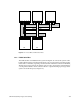
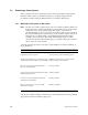
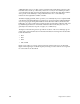
Figure 1-5 Polled Serial Bus
The polled serial bus provides a shortened error-reporting path to the System Controller
display on the front panel. The path from the bootmaster CPU to the RS-232 system console
port involves the Ebus and the IO4’s Ibus. For error messages to reach the graphics monitor,
they must pass through the graphics boards as well. Both of these error-reporting paths
require a significant percentage of the system’s hardware to be functional before an error
can be reported.
1.2.3 Interface Bus (Ibus) and Peripheral Bus (Pbus) on IO4 Board
When the PROM initializes, it reads the IA configuration registers to determine what kind
of devices are connected to the Ibus. On the basis of the configuration information, the
PROM runs a series of diagnostics that check the integrity of the Ibus and Pbus, as well as
the functionality of the devices themselves. These diagnostics cannot distinguish between
a bus failure and an ASIC failure, but they are sufficient to isolate a fault to the FRU (board)
level.
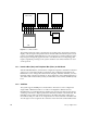
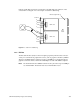
1.2.4 SCSI Bus
The system supports 20-MB-per-second SCSI buses. These buses can be configured as
single-ended or differential and as 8 or 16-bit. A five-digit drive address has been
implemented to accommodate the large number of storage devices the Everest board set
can manage. The first two digits represent the decimal slot number of the IO4 board. The
third digit corresponds to the nth SCSI channel on the IO4 board (with possible SCSI
mezzanine boards); zero and one are assigned to the two SCSI controllers on the IO4 board.
Two through seven are assigned to the controllers on the mezzanine cards installed on the
D D A D D
IP19/IP21
(Master CPU)
D D A D D
IP19/IP21
D D A D D
IP19/IP21
ID
IO4
ID IA ID ID
Polled Serial Bus
System
Controller
Status Panel