
Technical data


1-6 Theory of Operations
.
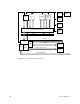
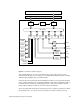
Figure 1-3 Everest System Buses
Each bus category is described in the following sections.
1.2.1 Everest Address and Data Buses
The Everest system buses consist of a 256-bit, 1200-MB/sec data bus, a 40-bit address bus,
and the bus interfaces. The interfaces between the system buses and the Everest boards are
supplied by a set of data and address ASICs (see Figure 1-4). There are four data ASICs (D
chips) and one address ASIC (A chip) on each board. This logic is not identical from board
to board but performs the same basic functions. Those interface chips perform parity
checking on the data, address, and control lines during every bus cycle. There are eight
parity lines on the data bus and two parity lines on the address bus. ASIC parity error
detection is explained in more detail in Section 2.4, “ASIC Error Detection.”
MC3
1
MC3
2
IP19/IP21
2
IP19/IP21
1 (Master
CPU)
System
Controller
Cooling
Fans
Offline
Switchers
Power
Boards
Everest Data Bus (256 bits)
Everest Address Bus (40 bits)
IO4
FMezz
SCSI
Mezz
Graphics
Board Set
SCSI
Devices
Ethernet
VME Bus
SCSI−1/SCSI−2 Buses
Flat Cable Interface
VCAM