
Technical data


1-4 Theory of Operations
sequence and display an error message. Error information is also provided by a series of
LEDs on the off-line switchers and the system boards, but these are not visible without
opening the cabinet.
The power-on tests execute whenever the system is powered on or reset. Those tests verify
enough of the system’s basic hardware functionality to load the standalone diagnostics
from the IDE.
The power-on diagnostics (POD) is a special command interpreter that is a subset of the
power-on tests. POD is automatically invoked by the PROM monitor in the event of an
error during the boot process, or can be manually selected by the operator. POD provides
an interface that allows the operator to inspect and modify various system parameters.
The standalone diagnostics are a series of functionality-oriented tests invoked from the
PROM Monitor. They provide the highest degree of error isolation and the most accurate
diagnosis but require their own environment (IDE) to run. Completion of the standalone
diagnostics provides sufficient confidence in the system to attempt to boot UNIX
, but is
not a guarantee.
Each group is described in detail in the following chapters.
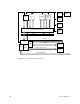
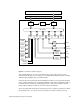
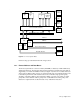
1.2 System Buses
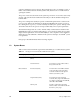
Table 1-1 lists each bus found in a typical Everest deskside (L) or rackmount (XL) system.
Table 1-1 Bus Types in Everest Deskside and Rackmount Systems
Bus Category Bus Types Description
Everest buses Everest data and address buses
(Ebus)
Interconnects the system board set.
Polled Serial bus Connects the system’s CPU boards to
the System Controller.
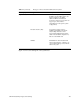
On-board buses Interface bus (Ibus) An internal bus on the IO4 board that
connects the Ebus to the peripheral
controllers and the board’s optional
interface (mezzanine) cards.
Peripheral bus (Pbus) Connects the Everest peripheral
controller (EPC) chip on the IO4 board
to a number of I/O ports, the NVRAM,
and 1 MB of flash PROM.
Memory bus Provides a path between the Ebus
interface ASICs on the MC3 board and
the memory array logic.