
Technical data


CHALLENGE/Onyx Diagnostic Road Map 1-3
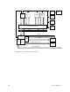
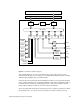
Figure 1-2 IO4 Functional Block Diagram
The available diagnostic tools are separated into six groups: parity checkers, power
subsystem self-checks, power-on tests, power-on diagnostics (POD), the System Controller,
and the integrated diagnostics environment (IDE).
Parity checkers are housed in the data and address bus ASICs on each system board, in the
cache controller and CPU cache on the IP19 and IP21 boards, and in each interface ASIC on
the IO4 board. The checkers are strategically placed to verify correct address and data
parity at the system bus connectors, as well as at the on-board buses.
The power subsystem self-checks are automatic at power on and reset. Voltages not within
the specified levels, or not present, cause the System Controller to halt the power-up
Everest Data Bus (256 bits)
Everest Address Bus (40 bits)
IA Chip Map RAM ID Chips
IBus (64 bits)
EPC
Chip
S1
Chip
F
Chip
F
Chip
Mezz
Slot
Mezz
Slot
PROM
NVRAM
Timer
Serial
Ports (4)
Kybd/
Mouse
Port
P
B
u
s
FCI
Chip
FCI
Chip
Fast/Wide
SCSI-2
Controller
Fast/Wide
SCSI-2
Controller
VCAM
Graphics
Board Set
SCSI
Devices
SCSI
Devices
Parallel Port
Ethernet
Controller