
Technical data


CHALLENGE/Onyx Diagnostic Road Map 5-33
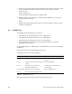
5.7.5 LED Power-On Status Codes
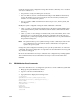
When the Power-on Diagnostics (POD) are running, a pair of LEDs from each bank of
processor LEDs will flash alternately. After POD runs and the system enters the PROM
monitor, the LEDs on the bootmaster CPU will display a fixed value (decimal 18, binary
010010). All other slave processors will loop on a pattern waiting for a command (see
Figure 5-10).
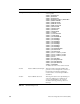
Figure 5-10 Slave Processor LED Pattern
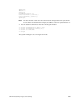
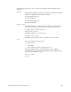
The bootmaster CPU will loop on the pattern shown in Figure 5-11 when polling the CC
UARTs.
Figure 5-11 CPU LED Pattern when Polling
5.8 Board Configuration Operations
This section describes the commands used to verify and/or change the system
configuration using the IO4 Boot PROM Monitor.
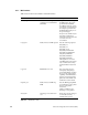
LSB O O O X X X MSB PLED_SCACHE_TAG_ADDR (56)
LSB X O O X X X MSB PLED_SCACHE_TAG_DATA (57)
LSB O X O X X X MSB PLED_SCACHE_ADDR (58)
LSB X X O X X X MSB PLED_SCACHE_DATA (59)
LSB O O X X X X MSB PLED_SCACHE_INIT (60)
LSB X O X X X X MSB PLED_SCACHE_INIT (61)
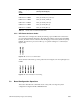
LED Pattern Displayed
X=Lit
O=Unlit
Description
(Flashing Value Displayed)
Table 5-8 IP21 Board Power-On Test Failure LEDs