
Technical data


xiii
Introduction
This document describes the various diagnostic tools available with the Everest board set
and their relationship to the Everest system components and to one another. This
document describes each of the diagnostic tools, the physical area of the system that they
test, and the possible error messages.
The information contained in this document is organized as follows:
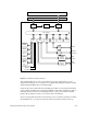
• Chapter 1, “Theory of Operations,” provides the theory of operations for the Everest
board set. The various buses connecting the boards are described, along with the
potential bus errors on each board.
• Chapter 2, “Diagnostic Procedures,” analyzes several fault-isolation procedures,
including how to examine a frozen system and how to examine the IRIX and system
controller error logs, and provides some general debugging hints. It also contains
diagrams showing where errors are detected on the system boards and lists error
messages.
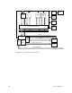
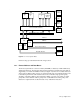
• Chapter 3, “Power Subsystem,” discusses the power subsystem, and illustrates the
inputs and outputs of all power supplies and on-board DC-to-DC converters. It also
describes the power-up sequence and the various fault LEDs and other
error-detection mechanisms.
• Chapter 4, “Using the System Controller,” explains the functions of the system
controller, what causes various error messages to be generated, and what those
messages mean.
• Chapter 5, “PROM Monitor,” describes the PROM monitor, as well as the power-on
tests and the power-on diagnostics (POD). System board configuration and the PROM
Monitor boot commands are also discussed.
• Chapter 6, “Interactive Diagnostics Environment (IDE),” supplies information on the
stand-alone IDE and IRIX error reporting.
• Chapter 7, “IRIX Error Reporting,” provides an overview of how the IRIX system
reports errors.