
Technical data

CHALLENGE/Onyx Diagnostic Road Map 5-25
5.7 CPU Board Fault/Status Indicators
The IP19 and IP21 CPU boards have one bank of six LEDs for each processor on the board.
Thus, a four processor CPU board has twenty-four banks of fault and status LEDs.
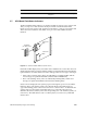
Figure 5-9 shows the location and orientation of the LEDs on a four-processor IP19 board.
The location and orientation of the LEDs on two processor IP19 and IP21 boards is
identical.
Figure 5-9 CPU Board Fault Indicators (IP19 Shown)
Each bank of LEDs displays forty-four status values and fifteen error values. The values are
displayed by the banks as a binary number, with the most significant bit represented by the
topmost LED (as viewed from the front of the cardcage). There are two types of messages:
• Status codes (constant values). These are indicated by constantly lit LEDs, and the
error messages are prefixed with PLED (which stands for PROM LED).
• Error codes (flashing values). These are indicated by flashing LEDs, and the error
messages are prefixed with FLED (which stands for flashing LED).
Status codes are displayed as the system progresses through the power-on tests and the
LEDs stay lit for each state the system passes through. Because the LEDs stay lit (as
opposed to flashing), status codes are also known as “constant values.” To determine the
system’s state, note the pattern of lit LEDs and use one of the following sections to
determine the status (constant) value and corresponding error code: For IP19 systems, see
Section 5.7.1, “IP19 LED Status Codes.” For IP21 systems, see Section 5.7.3, “IP21 LED
Status Codes.”
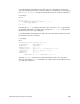
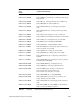
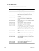
Error = 0000 0008 Multiple occurrence of Read correctable (Single
Bit) Error
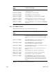
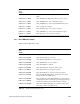
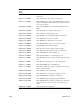
Leaf Error Field Value Description
Table 5-4 Leaf Error Field Values and Descriptions
Fault LEDs
(one bank of four)
3.3V Power
Brick
5.0V Power
Brick
MSB