
Technical data

5-24 PROM Monitor
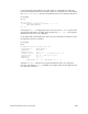
Locate all the MC3 boards and their slots. Then enter a dmc command for each MC3 slot,
where the argument is the hex slot number.
For example:
dmc 1
Configuration of the memory board in slot 01
EBus Error: 00000000
Leaf Enable: 0000000f
Bank Enable: 00000001
BIST Result: 00000000
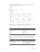
Leaf 0:
BIST = 00014000, Error = 00000000, ErrAddrHi = 00000000, ErrAddrLo = 00000000
Syndrome 0: 0000, Syndrome 1: 0000, Syndrome 2: 0000, Syndrome 3: 0000
Bank 0: Size = 00000001, Base = 00000000, IF = 00000000, IP = 00000000
Bank 1: Size = 00000007, Base = 00000000, IF = 00000000, IP = 00000000
Bank 2: Size = 00000007, Base = 00000000, IF = 00000000, IP = 00000000
Bank 3: Size = 00000007, Base = 00000000, IF = 00000000, IP = 00000000
Leaf 1:
BIST = 00000000, Error = 00000000, ErrAddrHi = 00000000, ErrAddrLo = 00000000
Syndrome 0: 0000, Syndrome 1: 0000, Syndrome 2: 0000, Syndrome 3: 0000
Bank 0: Size = 00000007, Base = 00000000, IF = 00000000, IP = 00000000
Bank 1: Size = 00000007, Base = 00000000, IF = 00000000, IP = 00000000
Bank 2: Size = 00000007, Base = 00000000, IF = 00000000, IP = 00000000
Bank 3: Size = 00000007, Base = 00000000, IF = 00000000, IP = 00000000
POD 03/00>
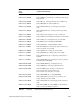
The field “EBus Error” is the “MA Ebus Error register,” described in Section 2.4, “ASIC
Error Detection.” Values for the EBus Error field are shown in Table 5-3:
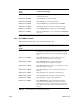
The field Error in the first line for each Leaf is the MA Leaf 0/1 Error Status register,
described in Section 2.4, “ASIC Error Detection.” Values for this Error field are shown in
Table 5-4
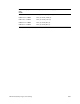
Ebus Error Field Value Description
0000 0001 EBus Data Error
0000 0002 EBus Address Error
0000 0004 My EBus Data Error
0000 0008 My EBus Address Error
Table 5-3 EBus Error Field Values and Descriptions
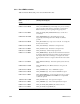
Leaf Error Field Value Description
Error = 0000 0001 Partial Write Uncorrectable (Multiple Bit) Error
Error = 0000 0002 Read Uncorrectable (Multiple Bit) Error
Error = 0000 0004 Read Correctable (Single Bit) Error
Table 5-4 Leaf Error Field Values and Descriptions