
Technical data

CHALLENGE/Onyx Diagnostic Road Map 5-23
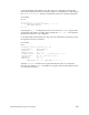
Locate all the IP19 boards and their slots. Then enter a dc command for each IP19 slot,
where the first argument is the hex slot number and the second argument is 6. This displays
the A Chip Error Register message as described in Section 2.4, “ASIC Error Detection.”
For example:
dc 3 6
Slot 03, Reg 06: 0000000000001000
*** Error/TimeOut Interrupt(s) Pending: 00000100 ==
EBus MyReq Addr Err
POD 03/00>
Following the Reg 06: hex display, the next two lines show the CC ERTOIP register of the
specific CPU where POD is executing; in this example it is slot 3 cpu 0. This register is
described in Section 2.4.1, “Error Messages.”
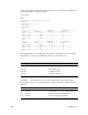
Locate all the IO4 boards and their slots. Then enter adio command for each IO4 slot, where
the argument is the hex slot number.
For example:
dio 5
Configuration of the IO board in slot 0x05
Large Window: 1, Small Window: 1
Endianness: Big Endian
Adapter Control: 0x00000002
Interrupt Vector: Level 0x00000003, Destination 0x00000040
Config status: HI: 0x00000d0d, LO: 0x0f0f0e00
IBUS Error: 0x00000000
EBUS Error1: 0x00000000
EBUS Err2Hi: 0x00007000 EBUS Err2Lo: 0x00000001
The field IBUS Error is the Ibus error register described in Section 2.4, “ASIC Error
Detection.” The field EBUS Error1 is the Ebus error register and is also described in Section
2.4, “ASIC Error Detection.”