
Technical data

5-10 PROM Monitor
5.3 Power-On Test Status Messages
This section lists of all of the status messages that are displayed by the System Controller
during the normal power-on process for IP19-based systems. IP21 systems vary slightly.
The messages are listed in the order in which they appear.
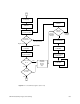
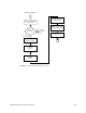
1. Starting System...
Displayed once bootmaster arbitration has completed. Indicates that the master
processor has started up correctly and is capable of communicating with the system
controller.
2. EBUS diags 2...
Displayed immediately before we run the secondary EBUS diagnostics. The
secondary EBUS diagnostics stress the interrupt logic and the EBUS.
3. PD Cache test...
Displayed immediately before we run the primary data cache test.
4. Building stack...
Displayed before we attempt to set up the cache as the stack. If this is the last message
displayed, there is probably something wrong with the master processor.
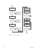
5. Jumping to MAIN...
Displayed before we switch into the C main subroutine.
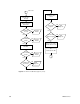
6. Initing Config Info...
Displayed before we attempt to do initial hardware probing and set up the everest
configuration information data structure. In this phase, we simply read out the
SYSCONFIG register and set the evconfig fields to rational default values.
7. Setting timeouts...
Displayed before we attempt to write to the various board timeout registers. Everest
requires that all of the boards be initialized with consistent timeout values, and that
these timeout values be written before we actually do reads or writes to the boards
(we’re safe so far because we have only touched configuration registers; this will
change when we start talking to IO4 devices).
8. Initing master IO4...
Displayed before we attempt to do basic initialization for all of the IO4’s in the
system. Basic initialization consists of writing the large and small window registers,
setting the endianess, setting up error interrupts, clearing the Ibus and Ebus error
registers, and examining the IO adapters.
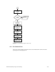
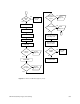
9. Initing EPC...
Displayed before we do the first writes to the master EPC. This routine clears the EPC
error registers and takes all EPC devices out of reset.
10. Initing EPC UART...
Displayed when we first enter the UART configuration code.
11. Initing UART Chan B...
Displayed before we begin initializing UART channel B’s control registers.
12. Initing UART Chan A...
Displayed before we begin initializing UART channel A’s control registers.